COOLING FAN
Cooling Fan Wiring Diagram for Mercury Tracer GS 1999
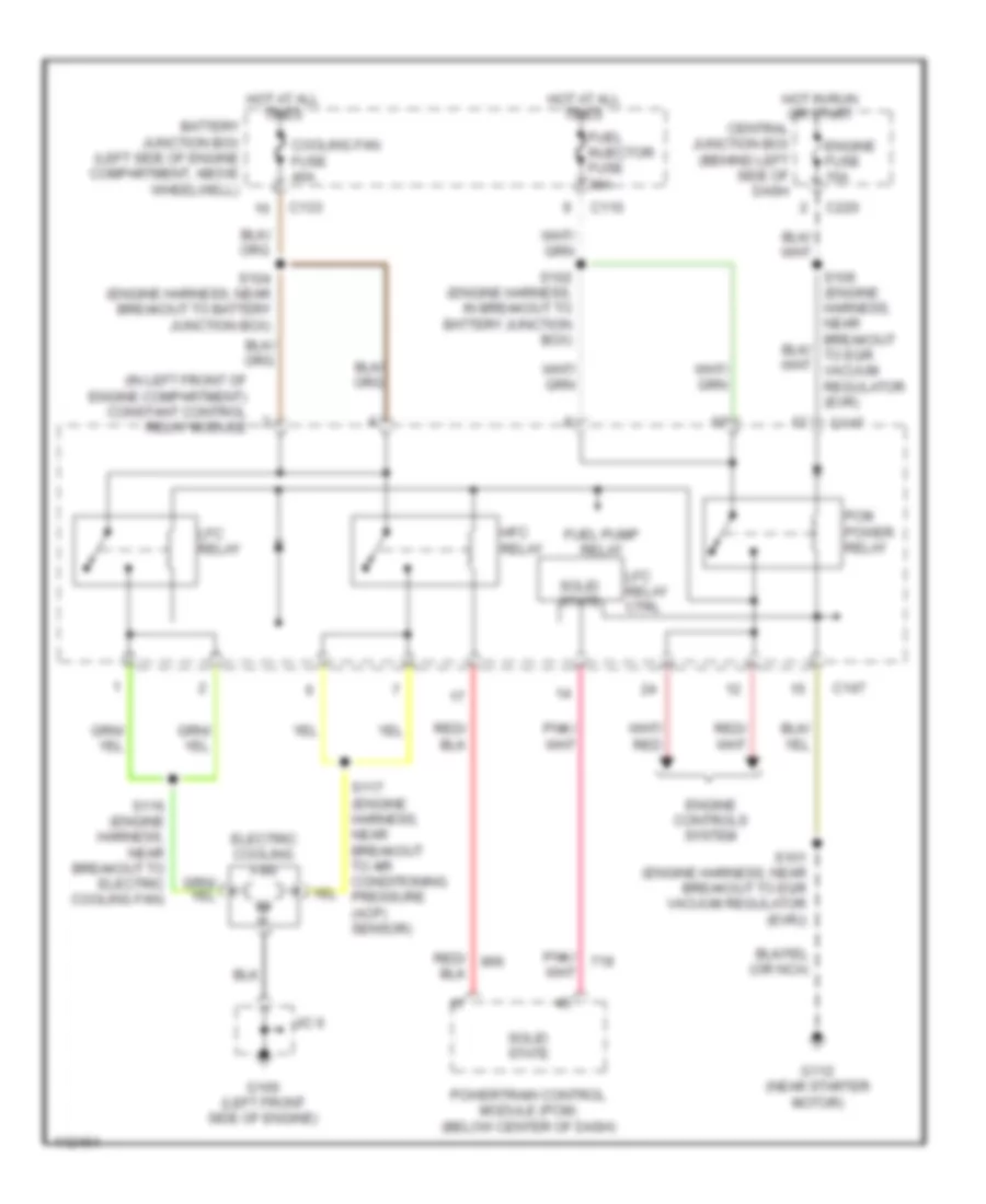
List of elements for Cooling Fan Wiring Diagram for Mercury Tracer GS 1999:
- (in left front of engine compartment) constant control relay module
- Battery junction box (left side of engine compartment, above wheelwell)
- C110
- C133
- C147
- C220
- Central junction box (behind left side of dash
- Cooling fan fuse 40a
- Electric cooling fan
- Engine controls system
- Engine fuse 15a
- Fuel injector fuse 30a
- Fuel pump relay
- G100 (left front side of engine)
- G112 (near starter motor)
- Hfc relay
- Hot at all times
- Hot in run or start
- J/c 6
- Lfc relay
- Lfc relay ctrl
- Pcm power relay
- Powertrain control module (pcm) (below center of dash)
- S101 (engine harness, near breakout to egr vacuum regulator (evr))
- S102 (engine harness, in breakout to battery junction box)
- S104 (engine harness, near breakout to battery junction box)
- S116 (engine harness, near breakout to electric cooling fan)
- S117 (engine harness, near breakout to air conditioning pressure (acp) sensor)
- Solid state
 English