COOLING FAN
Cooling Fan Wiring Diagram, Evolution for Mitsubishi Lancer ES 2003

List of elements for Cooling Fan Wiring Diagram, Evolution for Mitsubishi Lancer ES 2003:
- (mounted on rear of radiator)
- A17
- A17-1
- A34
- A35
- C115
- C119
- C121
- C210
- Condenser fan motor
- Condenser fan relay (hi) (on engine compt relay box)
- Condenser fan relay (lo) (on engine compt relay box)
- Cooling fan motor
- Engine compartment relay box (on left side of engine compt)
- Engine control module (behind glove box)
- Engine controls system
- Engine coolant temperature sensor (on rear of cylinder head)
- Fan control module (on fan shroud, at left front of engine compt)
- Fan control relay (on engine compartment relay box)
- Fuse 11 30a
- Fuse 25 30a
- Fuse 5 7.5a
- Fuse 8 20a
- Fusible link 2 50a
- G13 (at left front corner of engine compt)
- Headlights, exterior lights & wiper/washer systems
- Hot in all times
- Hot in on
- Joint connector 2 (behind instrument cluster)
- Joint connector 6 (behind lower center of dash)
- Mfi relay (on engine compartment relay box)
- Nca
- Red
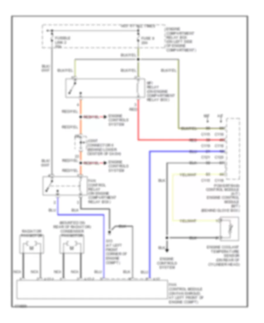
Cooling Fan Wiring Diagram, Except Evolution for Mitsubishi Lancer ES 2003
List of elements for Cooling Fan Wiring Diagram, Except Evolution for Mitsubishi Lancer ES 2003:
- (mounted on rear of radiator) condenser fan motor
- A/t
- A17
- A17-1
- A17-2
- C115
- C118
- C119
- C120
- C121
- Engine compartment relay box (on left side of engine compartment)
- Engine controls system
- Engine coolant temperature sensor (on rear of cylinder head)
- Fan control module (on fan shroud, at left front of engine compt)
- Fan control relay (on engine compartment relay box)
- Fuse 8 20a
- Fusible link 2 50a
- G13 (at left front corner of engine compt)
- Hot at all times
- Joint connector 6 (behind lower center of dash)
- M/t
- Mfi relay (on engine compartment relay box)
- Nca
- Powertrain control module (a/t) engine control module (m/t) (behind glove box)
- Radiator fan motor
- Red