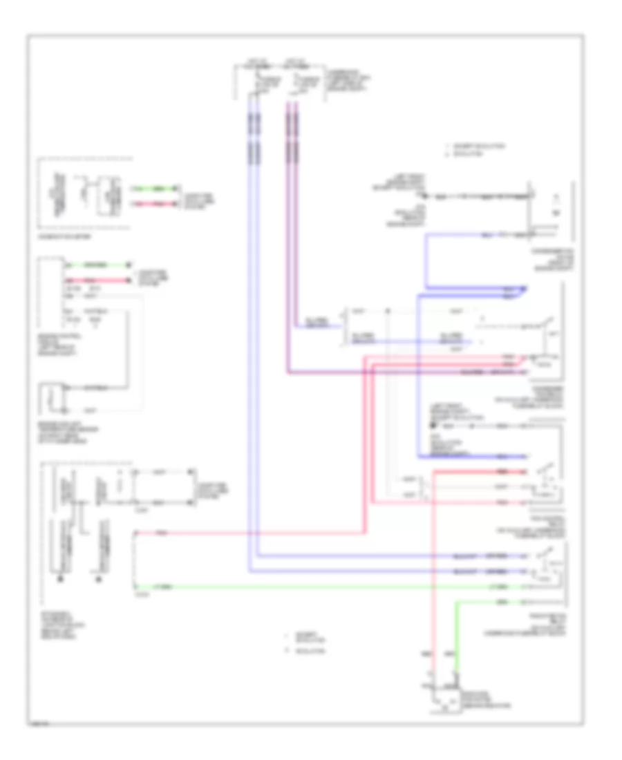
COOLING FAN
2.0L
2.0L, Cooling Fan Wiring Diagram for Mitsubishi Lancer ES 2014

List of elements for 2.0L, Cooling Fan Wiring Diagram for Mitsubishi Lancer ES 2014:
- (engine coolant lcd
- (left front engine compt) g17
- Analog interface circuit
- B-108
- B-109
- C-301
- C-312
- Can
- Can drive circuit
- Combination meter
- Computer data lines system
- Condenser fan motor (front of engine compt)
- Condenser fan relay (on underhood fuse/relay block)
- Cpu
- Engine control module (left rear of engine compt)
- Engine coolant temperature sensor (on right rear of cylinder head)
- Etacs-ecu (on rear of junction block, behind left end of dash)
- Fan control relay (on underhood fuse/relay block)
- Fusible link 28 30a
- Fusible link 29 40a
- Hot at all times
- Interface circuit
- Nca
- Pnk
- Radiator fan motor (behind radiator)
- Radiator fan relay (on underhood fuse/relay block)
- Red
- Temperature)
- Transceiver circuit
- Underhood fuse/relay box (left side of engine compt)
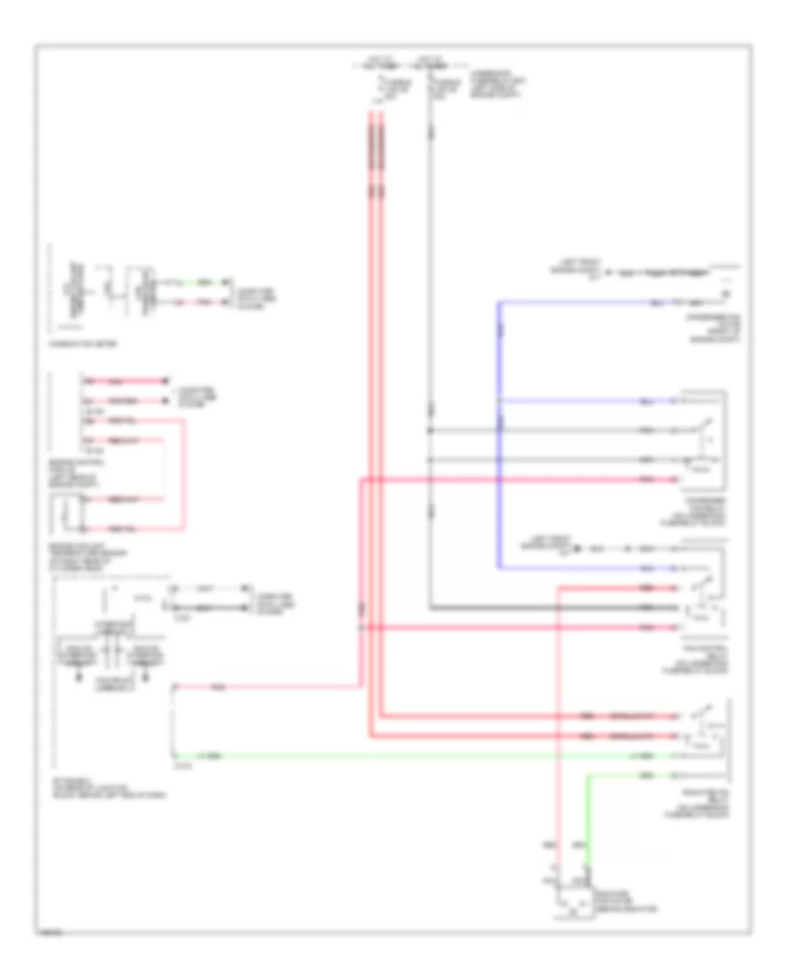
2.0L TURBO
2.0L Turbo, Cooling Fan Wiring Diagram for Mitsubishi Lancer ES 2014
List of elements for 2.0L Turbo, Cooling Fan Wiring Diagram for Mitsubishi Lancer ES 2014:
- (engine coolant lcd
- (left front engine compt) (except evolution) g17
- (or red)
- Analog interface
- B-09
- B-10
- B-108
- B-109
- C-301
- C-312
- Can
- Can drive circuit
- Circuit
- Circuit interface
- Combination meter
- Computer data lines system
- Condenser fan motor (front of engine compt)
- Condenser fan relay (on auxiliary underhood fuse/relay block)
- Cpu
- Engine control module (left rear of engine compt)
- Engine coolant temperature sensor (on right rear of cylinder head)
- Etacs-ecu (on rear of junction block, behind left end of dash)
- Evolution
- Except evolution
- Fan control relay (on auxiliary underhood fuse/relay block)
- Fusible link 28 30a
- Fusible link 29 40a
- G16 (evolution) (rear of engine compt)
- Hot at all times
- Nca
- Pnk
- Radiator fan motor (behind radiator)
- Radiator fan relay (on auxiliary underhood fuse/relay block)
- Red
- Temperature)
- Transceiver circuit
- Underhood fuse/relay box (left side of engine compt)
2.4L
2.4L, Cooling Fan Wiring Diagram for Mitsubishi Lancer ES 2014
List of elements for 2.4L, Cooling Fan Wiring Diagram for Mitsubishi Lancer ES 2014:
- (engine coolant lcd
- (left front engine compt) g17
- Analog interface circuit
- B-108
- B-109
- C-301
- C-312
- Can
- Can drive circuit
- Combination meter
- Computer data lines system
- Condenser fan motor (front of engine compt)
- Condenser fan relay (on underhood fuse/relay block)
- Cpu
- Engine control module (left rear of engine compt)
- Engine coolant temperature sensor (on right rear of cylinder head)
- Etacs-ecu (on rear of junction block, behind left end of dash)
- Fan control relay (on underhood fuse/relay block)
- Fusible link 28 30a
- Fusible link 29 40a
- Hot at all times
- Interface circuit
- Nca
- Pnk
- Radiator fan motor (behind radiator)
- Radiator fan relay (on underhood fuse/relay block)
- Red
- Temperature)
- Transceiver circuit
- Underhood fuse/relay box (left side of engine compt)