COOLING FAN
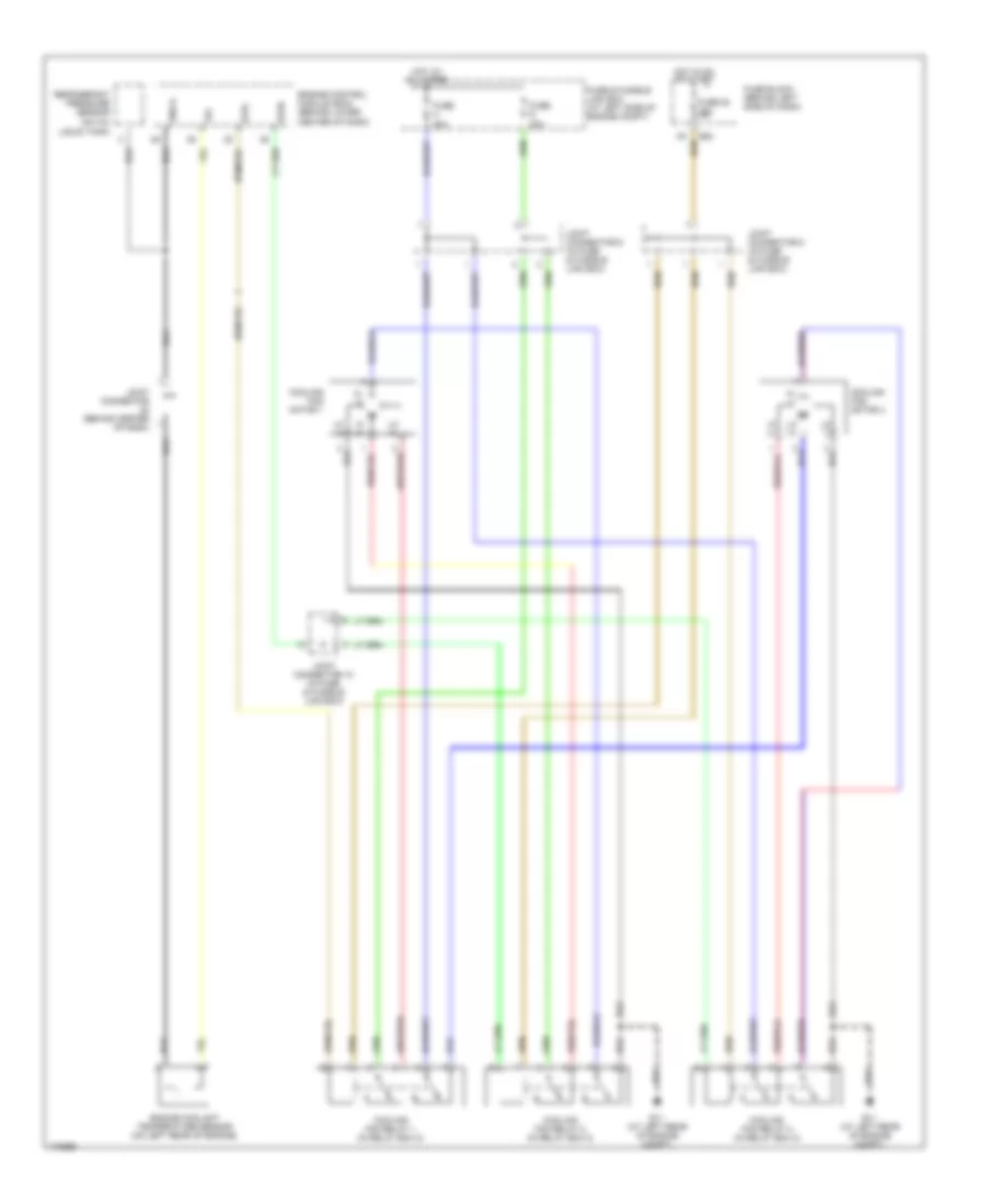
Cooling Fan Wiring Diagram for Nissan Maxima GXE 2003
List of elements for Cooling Fan Wiring Diagram for Nissan Maxima GXE 2003:
- Cooling fan motor 1
- Cooling fan motor 2
- Cooling fan relay 1 (in relay box 2)
- Cooling fan relay 2 (in relay box 2)
- Cooling fan relay 3 (in relay box 2)
- E11 (at left rear of engine compt)
- E83
- Engine control module (ecm) (behind lower center of dash)
- Engine coolant temperature sensor (on left rear of engine)
- Fuse & fusible link box (at left side of engine compt)
- Fuse 20 15a
- Fuse block (behind left side of dash)
- Fuse g 40a
- Fuse h 40a
- Gnd-a
- Hi (+)
- Hi (-)
- Hot at all times
- Hot in on or start
- Joint connector (behind center of dash)
- Joint connector 10 (in fuse & fusible link box)
- Joint connector 8 (in fuse & fusible link box)
- Joint connector 9 (in fuse & fusible link box)
- Lo (+)
- Lo (-)
- Refrigerant pressure sensor (on a/c liquid tank)
- Rfrh
- Rfrl
 English