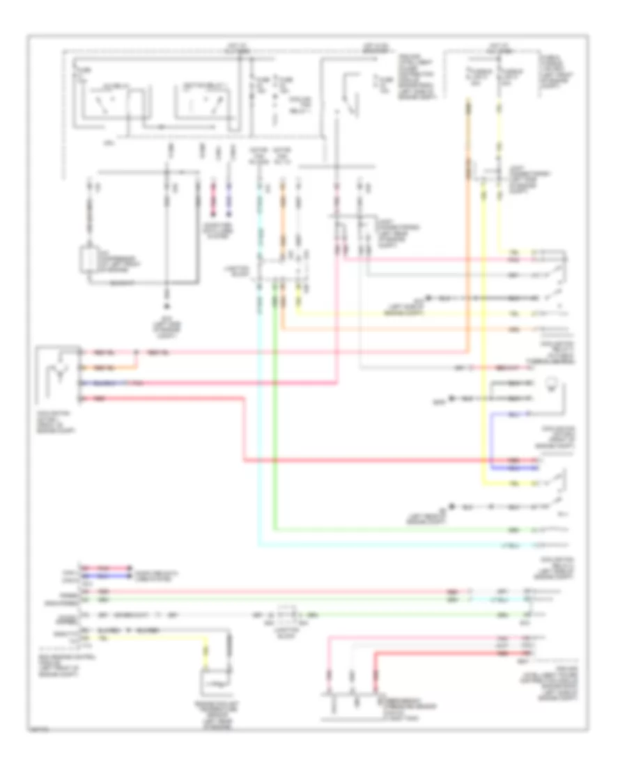
COOLING FAN
Cooling Fan Wiring Diagram for Nissan Maxima S 2009
List of elements for Cooling Fan Wiring Diagram for Nissan Maxima S 2009:
- A/c compressor (at left front of engine)
- A/c relay
- Avcc2
- Avcc2- pdpres
- Can-h
- Can-l
- Computer data lines system
- Cooling fan motor-1 (front of engine compt)
- Cooling fan motor-2 (front of engine compt)
- Cooling fan relay 1
- Cooling fan relay-2 (left side of engine compt)
- Cooling fan relay-3 (in fuse & fusible link box)
- Cpu
- E10
- E15 (left side of engine compt)
- E17
- E18
- E201
- E209
- E44
- E45
- E47
- E48
- E9 (left rear of engine compt)
- Ecm (engine control module) (left front of engine compt)
- Engine coolant temperature sensor (left rear of engine)
- F10
- F13
- Fuse & fusible link box (left front of engine compt)
- Fuse 10a
- Fuse 15a
- Fusible link k 40a
- Fusible link m 40a
- Gnd
- Gnda-pdres
- Gnda-tw
- Hot at all times
- Hot in on or start
- Ignition relay 1
- Ipdm e/r (intelligent power distribution module engine room) (left side of engine compt)
- Joint connector-e01 (left side of engine compt)
- Joint connector-e02 (left rear of engine compt)
- Junction block
- Motor fan rly hi
- Motor fan rly mid
- P-gnd
- Pdres
- Pnk
- Red
- Refrigerant pressure sensor (on a/c liquid tank)
- S-gnd
- Sig
 English