COOLING FAN
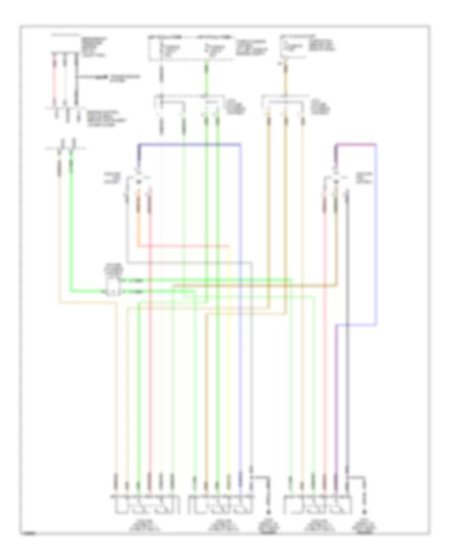
Cooling Fan Wiring Diagram for Nissan Maxima SE 2000
List of elements for Cooling Fan Wiring Diagram for Nissan Maxima SE 2000:
- (in fuse & fusible link box) j/c 10
- Avcc
- Cooling fan motor 1
- Cooling fan motor 2
- Cooling fan relay 1 (in relay box 2)
- Cooling fan relay 2 (in relay box 2)
- Cooling fan relay 3 (in relay box 2)
- Engine control module (ecm) (behind instrument lower cover)
- Fuse & fusible link box (at left side of engine compt)
- Fuse 20 15a
- Fuse block (behind left side of dash)
- Fusible link g 40a
- Fusible link h 40a
- G100 (front of left front fender)
- G101 (front of right front fender)
- Gnd-a
- Hot at all times
- Hot in on & start
- J/c 8 (in fuse & fusible link box)
- J/c 9 (in fuse & fusible link box)
- Pdpres
- Red
- Refrigerant pressure sensor (on a/c liquid tank)
- Rfrh
- Rfrl
- Transmissions system
 English