COOLING FAN
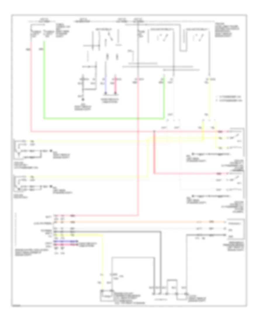
Cooling Fan Wiring Diagram for Nissan NV1500 SV 2013
List of elements for Cooling Fan Wiring Diagram for Nissan NV1500 SV 2013:
- 4.0l
- 5.6l
- Avcc (pd press)
- Batt
- Can-h
- Can-l
- Computer data lines system
- Cooling fan motor 1 (w/o passenger van)
- Cooling fan motor 2
- Cooling fan relay 1
- Cooling fan relay 2
- Cooling fan relay 3 (w/ passenger van) (in fuse holder-2)
- Cooling fan relay 4 (w/ passenger van) (in fuse holder-2)
- Cpu
- E120
- E121
- E122
- E124
- E15 (right rear of engine compt)
- E16
- E24 (left rear of engine compt)
- E77
- Engine control module (ecm) (right rear corner of engine compt)
- Engine coolant temperature sensor (4.ol: rear of right cylinder bank) (5.6l: top front of engine)
- F14
- F203
- F36
- F54
- F72
- Fuse & fusible link box (right rear of engine compt)
- Fuse 20a
- Fusible link m 40a
- Fusible link p 40a
- Gnd
- Gnd a
- Hot at all times
- Hot in on or start
- Ignition relay
- Ipdm e/r (intelligent power distribution module engine room) (right rear of engine compt)
- J/c f01 (right rear of engine compt)
- Pd press
- Pnk
- Pwr suply
- Red
- Refrigerant pressure sensor (left front of engine compt)
- Sig
- W/ passenger van
- W/o passenger van
 English