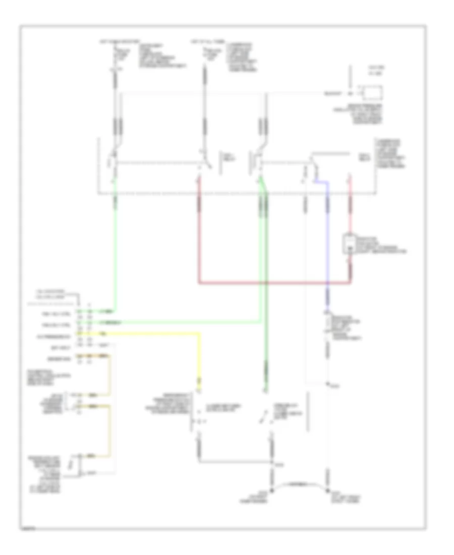
COOLING FAN
Cooling Fan Wiring Diagram for Pontiac Vibe GT 2006
List of elements for Cooling Fan Wiring Diagram for Pontiac Vibe GT 2006:
- 1.8l (vin 8) fwd
- 1.8l (vin l) awd
- A/c pressure sw
- Brake pressure modulator valve (bpmv) (at right front side of engine compartment)
- Closed between 28 psi & 455 psi
- Ect input
- Ecu-ig fuse 10a
- Engine coolant temperature (ect) sensor (1.8l (vin l): at rear of engine) (1.8l (vin 8): at left side of cylinder head)
- Fan 1 relay
- Fan 1 rly ctrl
- Fan 2 relay
- Fan 2 rly ctrl
- G102 (on right inner fender)
- G103 (at left front strut tower)
- Hot at all times
- Hot in run or start
- Instrument panel fuse block (left of steering column, behind storage compartment)
- Open below 178 psi closed above 220 psi
- Powertrain control module (pcm) (behind right side of dash)
- Radiator fan motor (at front of engine compt, behind radiator)
- Radiator fan resistor (at left front of engine compartment)
- Rdi fan fuse 40a
- Refrigerant pressure switch (at right side of engine compartment, on receiver drier)
- S102
- S103
- Sensor gnd
- Sp108 (in engine accessory harness, near pcm)
- Underhood fuse block (left side of engine compartment, mounted to inner fender)
- W/ vsc
- W/o vsc
 English