COOLING FAN
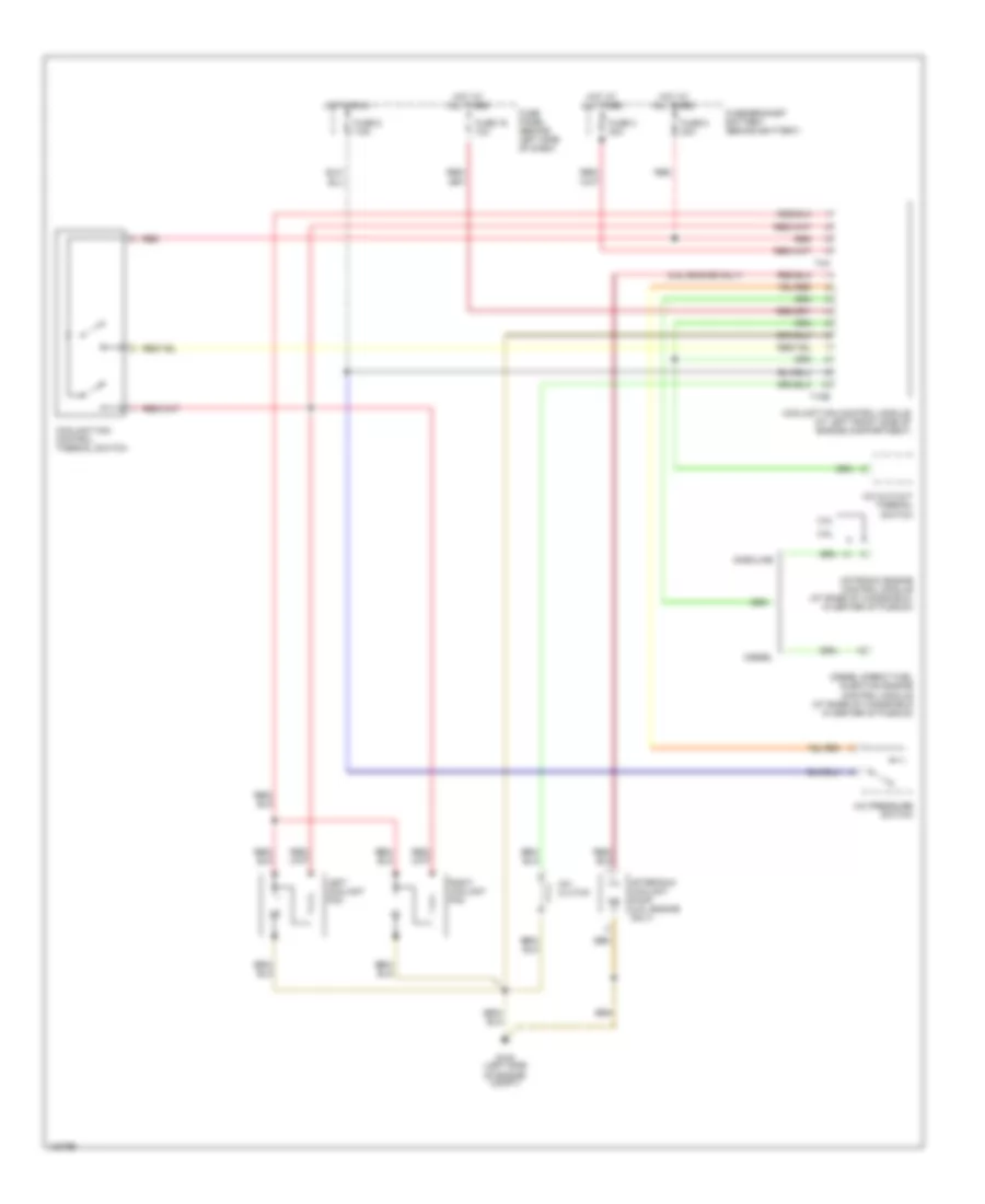
Cooling Fan Wiring Diagram, Auto A/C for Volkswagen GTI VR6 1999

List of elements for Cooling Fan Wiring Diagram, Auto A/C for Volkswagen GTI VR6 1999:
- A/c clutch
- A/c cut-out thermal switch
- A/c pressure switch
- After-run coolant pump
- Climatronic control module
- Coolant fan control module (at left front side of engine compartment)
- Coolant fan control thermal switch
- Fuse 16 10a
- Fuse 3 30a
- Fuse 5 7.5a
- Fuse 8 30a
- Fuse panel (behind left side of dash)
- Fuse/bracket battery (behind battery)
- G100 (left side of engine compt)
- Hot at all times
- Hot in run
- Left coolant fan
- Red
- Right coolant fan
- T10b
- T4a
Cooling Fan Wiring Diagram, Manual A/C for Volkswagen GTI VR6 1999
List of elements for Cooling Fan Wiring Diagram, Manual A/C for Volkswagen GTI VR6 1999:
- (2.8l engine only)
- 2.0l
- 2.8l
- A/c clutch
- A/c cut-out thermal switch
- A/c pressure switch
- After-run coolant pump (2.8l engine only)
- Coolant fan control module (at left front side of engine compartment)
- Coolant fan control thermal switch
- Diesel
- Diesel direct fuel injection engine control module (at base of windshield in center of plenum)
- Fuse 16 10a
- Fuse 3 30a
- Fuse 5 7.5a
- Fuse 8 30a
- Fuse panel (behind left side of dash)
- Fuse/bracket battery (behind battery)
- G100 (left side of engine compt)
- Gasoline
- Hot at all times
- Hot in run
- Left coolant fan
- Motronic engine control module (at base of windshield, in center of plenum)
- Red
- Right coolant fan
- T10b
- T4a