
COOLING FAN
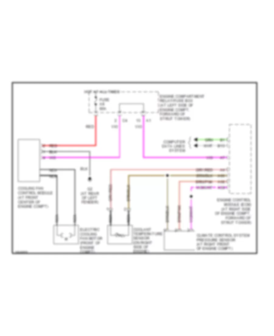
Cooling Fan Wiring Diagram for Volvo XC90 2004
List of elements for Cooling Fan Wiring Diagram for Volvo XC90 2004:
AIR CONDITIONINGANTI-LOCK BRAKESCRUISE CONTROLANTI-THEFTCOOLING FANCOMPUTER DATA LINESELECTRONIC POWER STEERINGGROUND DISTRIBUTIONDEFOGGERSEXTERIOR LIGHTSENGINE PERFORMANCEINTERIOR LIGHTSHEADLIGHTSINSTRUMENT CLUSTERMEMORY SYSTEMSHORNNAVIGATIONPOWER DISTRIBUTIONPOWER TOP/SUNROOFPOWER DOOR LOCKSPOWER MIRRORSPOWER SEATSSHIFT INTERLOCKSTARTING/CHARGINGPOWER WINDOWSRADIOTRANSMISSIONWARNING SYSTEMSSUPPLEMENTAL RESTRAINTSWIPER/WASHERBODY CONTROL MODULES