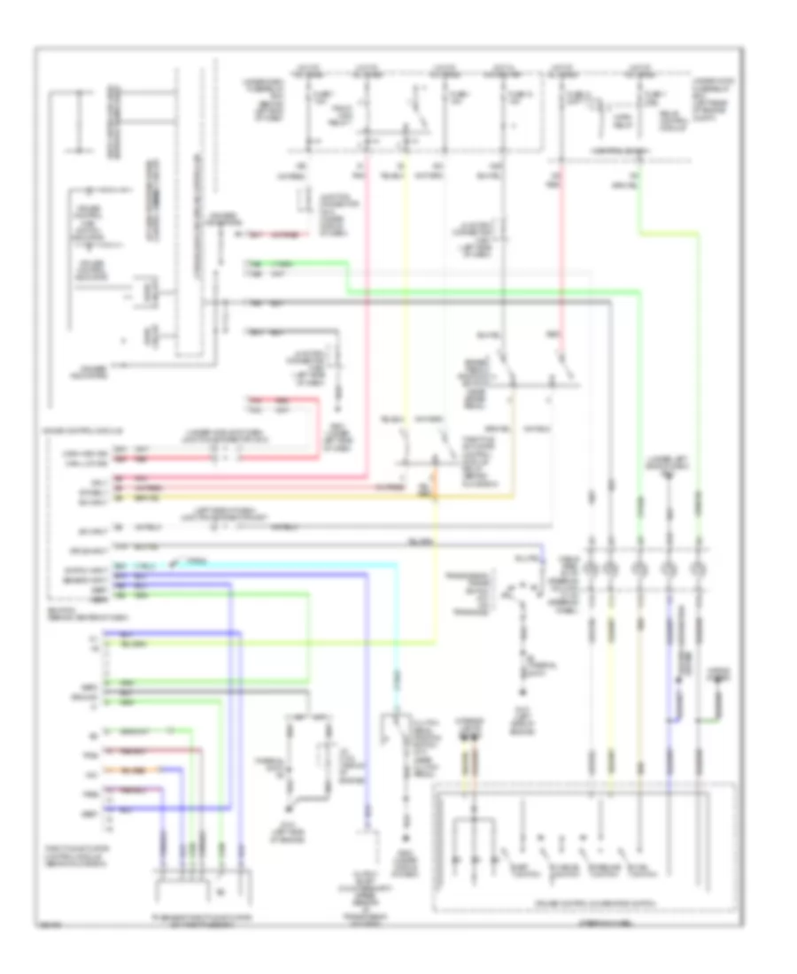
CRUISE CONTROL
Cruise Control Wiring Diagram for Acura TL 2007
List of elements for Cruise Control Wiring Diagram for Acura TL 2007:
- (left side of dash) junction connector c507
- (thermal joint) s2
- (under left side of dash) g501
- (under middle of dash) junction connector c512
- A/t
- A13
- A14
- A25
- A26
- A28
- A29
- A30
- B10
- B15
- B17
- B19
- Brake pedal position switch (near brake pedal)
- C11
- C12
- C13
- C14
- C19
- Cable reel (b: on steering column) (c: on steering wheel)
- Cancel switch
- Canh high sig
- Canl low sig
- Clutch pedal position switch (m/t) (near clutch pedal)
- Control block
- Control dimming circuit a/t gear position/cruise
- Cpu/fail safe circuit/can controller
- Cruise control combination switch
- Cruise control indicator
- Cruise control main switch indicator
- Drive circuit
- Drive input
- E15
- E26
- E30
- Ecm/pcm (behind center of dash)
- Etcsrly
- Fuse 1 15a
- Fuse 13 20a
- Fuse 18 15a
- Fuse 7 7.5a
- G101 (left side of engine)
- G501 (under left side of dash)
- G503 (under middle of dash)
- Gauge control module
- Gauges/ indicators
- Ground
- Ground distribution system
- Horn relay
- Horns system
- Hot at all times
- Hot in on or start
- Interior lights system
- J/c c104 (middle of engine)
- Junction connector c507 (left side of dash)
- Junction connector c508 (left side of dash)
- Junction connector c510 (under middle of dash)
- M/t
- Main switch
- Mrly
- N29
- Network transceiver fast controller area
- Output shaft (countershaft) speed sensor (in transmission housing)
- Pgm-fi main relay 1
- Pnk
- Red
- Relay control module
- Resume switch
- S2 (thermal joint)
- Sedf
- Sefd
- Sensor input
- Set switch
- Steering wheel
- Sw input
- Switch input
- Throttle actuator control module (behind glove box)
- Throttle actuator control module relay (behind glove box)
- Tp sensor/throttle actuator (on throttle body)
- Tpsa
- Tpsb
- Transmission range switch (a/t) (on transaxle)
- Type s
- Under-dash fuse/relay box (behind left end of dash)
- Under-hood fuse/relay box (left rear of engine compt)
- Vcc
- X23
- X35
 English