CRUISE CONTROL
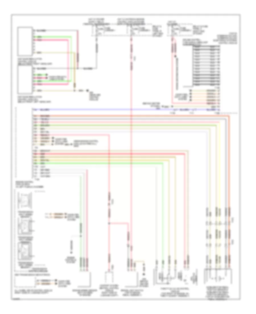
Cruise Control Wiring Diagram for Audi S6 2014
List of elements for Cruise Control Wiring Diagram for Audi S6 2014:
- (behind center of dash) g45
- (near engine control module on firewall) g645
- (top of steering column) steering column electronic systems control module
- Accelerator pedal position sensor & accelerator pedal position sensor 2 (top of accelerator pedal assembly)
- All wheel drive control module (right side of luggage compt)
- Brake light switch (top of brake pedal assembly)
- Comfort system central control module (right side of luggage compt)
- Computer data lines system
- Cruise control/ turn signal/headlamp flasher switch
- Distance regulation control module (below front right headlamp)
- Distance regulation control module 2 (below front left headlamp)
- Dsg transmission mechatronic
- Engine control module (ecm) (in left plenum chamber)
- Engine controls system
- Engine speed sensor (bottom rear of engine)
- Epc throttle drive
- Fuse 10a
- Fuse 5a
- Fuse carrier 1
- Fuse carrier 2
- Fuse carrier 3
- G45 (behind center of dash)
- G55 (near abs control module)
- Hot at all times
- Nca
- Pnk
- Power distribution system
- Red
- Relay & fuse panel b (left end of dash)
- Relay & fuse panel c (right end of dash)
- Sensor 1 angle
- Sensor 2 angle
- T105
- T13b
- T16e
- T17a
- T17b
- T17h
- T17i
- T17o
- T32g
- T91
- Throttle valve control module (top front of engine, on throttle body assembly)
- Transmission control module
- Transmission input speed sensor 1
- Transmission input speed sensor 2
- Transmission input speed sensor 3
 English