CRUISE CONTROL
4.4L VIN D
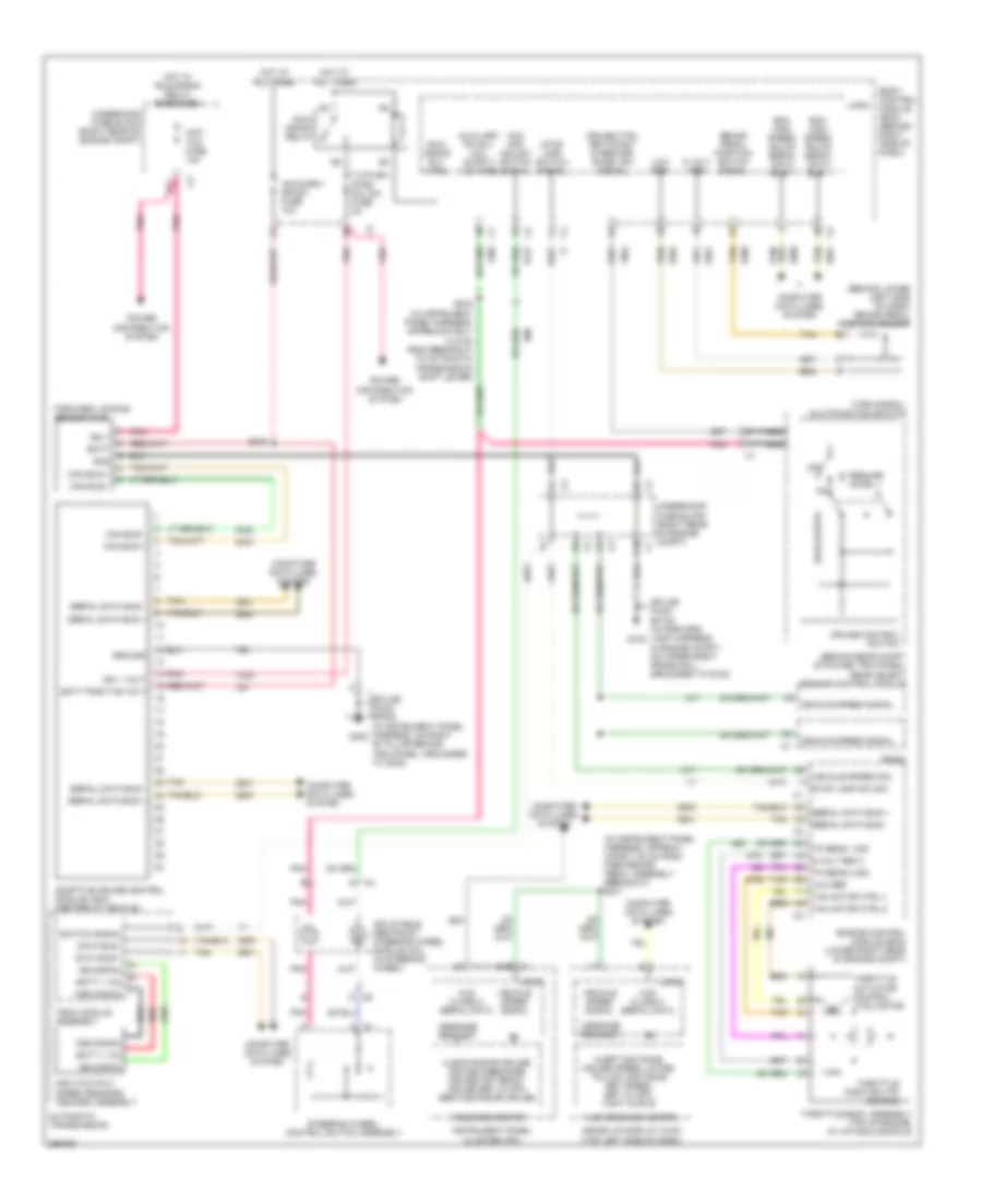
4.4L VIN D, Conventional Cruise Control Wiring Diagram for Cadillac XLR V 2007

List of elements for 4.4L VIN D, Conventional Cruise Control Wiring Diagram for Cadillac XLR V 2007:
- (behind lower left side of dash) brake pedal position sensor
- (behind rear compt stowage trim panel) rear object sensor control module
- (not used)
- (not used) c1
- (right side of engine compt, under battery) g104
- 5 volt ref
- 5-volt ref-1
- 5-volt ref-2
- A iss signal
- A15
- Acc gap adjust switch signal
- Acceleration pedal position (app) sensor (top of accelerator pedal assembly)
- App sen 1 sig
- App sen 2 sig
- Automatic transmission
- B batt + vol
- Batt + vol
- Batt5 fuse 30a
- Battery positive voltage
- Body control module (bcm) (behind right right side of dash)
- Brake pedal position switch signal
- C oss signal
- Computer data lines system
- Cruise control switch
- Cruise ctrl set/coast & resume/ accel sw signal
- Cruise speed set xxx
- D12
- Data bus +
- Data bus -
- Engine control module (ecm) (lower right rear of engine compt)
- Ground
- Heads up display (hud) (top left side of dash)
- High speed gmlan serial data bus +
- High speed gmlan serial data bus -
- Hot at all times
- Hud message center
- Inflatable restraint steering wheel module coil (in steering wheel)
- Input/output speed sensors (iss/oss) assembly
- Instrument panel cluster (ipc)
- Iss signal
- Logic
- Low ref
- Low reference
- Message request
- Nca
- Off
- Oss signal
- Pnk
- Radio
- Red
- Resume/ accel +
- S211 (in instrument panel harness, approximately 25 cm from park brake pedal assembly breakout)
- S232
- S276 (in instrument panel harness, approximately 14.5 cm from breakout to automatic transmission shift lever)
- Serial data bus +
- Serial data bus -
- Set/coast
- Stop lamp sw sig
- Stop lamp switch signal
- Switch signal
- Tac motor ctrl-1
- Tac motor ctrl-2
- Tan
- Tehc module assembly
- Throttle actuator control (tac) motor
- Throttle body assembly (top of engine, at intake manifold)
- Throttle position (tp) sensor
- Tp sen 1 sig
- Tp sen 2 sig
- Turn signal/ multifunction switch
- Underhood fuse block (right rear of engine compt)
- Vehicle speed sig
- Vehicle speed signal
- Vehicle speed signal hud class 2 serial data
4.6L VIN A
4.6L VIN A, Adaptive Cruise Control Wiring Diagram for Cadillac XLR V 2007
List of elements for 4.6L VIN A, Adaptive Cruise Control Wiring Diagram for Cadillac XLR V 2007:
- (behind lower left side of dash) brake pedal position sensor
- (behind rear compt stowage trim panel) rear object sensor control module
- (in instrument panel harness, approxi- mately 25 cm from park brake pedal assembly breakout) s211
- 5 volt ref
- 5-volt ref 2
- A iss signal
- Acc gap adjust switch signal
- Acc/ tcm fuse 10a
- Acca/driv dr sw fuse 10a
- Adaptive cruise control module (acm) (center of vehicle)
- Alert distance cruise speed limited follow distance set speed set xx mph tight curve
- Automatic transmission
- B batt + vol
- Batt
- Batt + vol
- Batt positive volt
- Bcm high speed gmlan serial data bus +
- Bcm high speed gmlan serial data bus -
- Body control module (bcm) (behind right side of dash)
- Brake pedal position switch signal
- C oss signal
- C1 a15
- C10
- C5 d
- Can bus +
- Can bus -
- Clean radar cruise cruise disengage cruise not ready cruise set xx mph service radar cruise
- Computer data lines system
- Cruise control switch
- Cruise ctrl set/coast & resume/ accel sw signal
- Data bus +
- Data bus -
- E11
- Engine control module (ecm) (lower right rear of engine compt)
- Forward looking sensor (fls)
- G102
- G302
- Gnd
- Ground
- Heads up display (hud) (top left side of dash)
- Hot at all times
- Hot w/ run/crank relay energized
- Hud class 2 serial data
- Hud message center
- Ign 1
- Ign 1 volt
- Inflatable restraint steering wheel module coil (in steering wheel)
- Input/output speed sensors (iss/oss) assembly
- Instrument panel cluster (ipc)
- Iss signal
- Logic
- Low ref
- Message center
- Message request
- Nca
- Off
- Oss signal
- Pnk
- Power distribution system
- Radio
- Red
- Resume/ accel +
- Run/ crank relay
- Run/ crank rly ctrl
- S240
- S276 (in instrument panel harness, approximately 14.5 cm from breakout to automatic transmission shift lever)
- Serial data bus +
- Serial data bus -
- Set/coast
- Splice pack sp102 (in forward lamp harness, in engine compt, on upper right frame rail, grounded to g102)
- Splice pack sp302 (in instrument panel harness, on right "b" pillar behind trim panel, grounded to g302)
- Steering wheel control switch assembly
- Stop lamp sw sig
- Stop lamp switch signal
- Switch signal
- Tac motor ctrl-1
- Tac motor ctrl-2
- Tan
- Tehc module assembly
- Throttle actuator control (tac) motor
- Throttle body assembly (top of engine, at intake manifold)
- Throttle position (tp) sensor
- Tp sens 1 sig
- Tp sens 2 sig
- Turn signal/ multifunction switch
- Tutd sw/ strg col sw fuse 2a
- Underhood fuse block (right rear of engine compt)
- Vehicle speed sig
- Vehicle speed signal