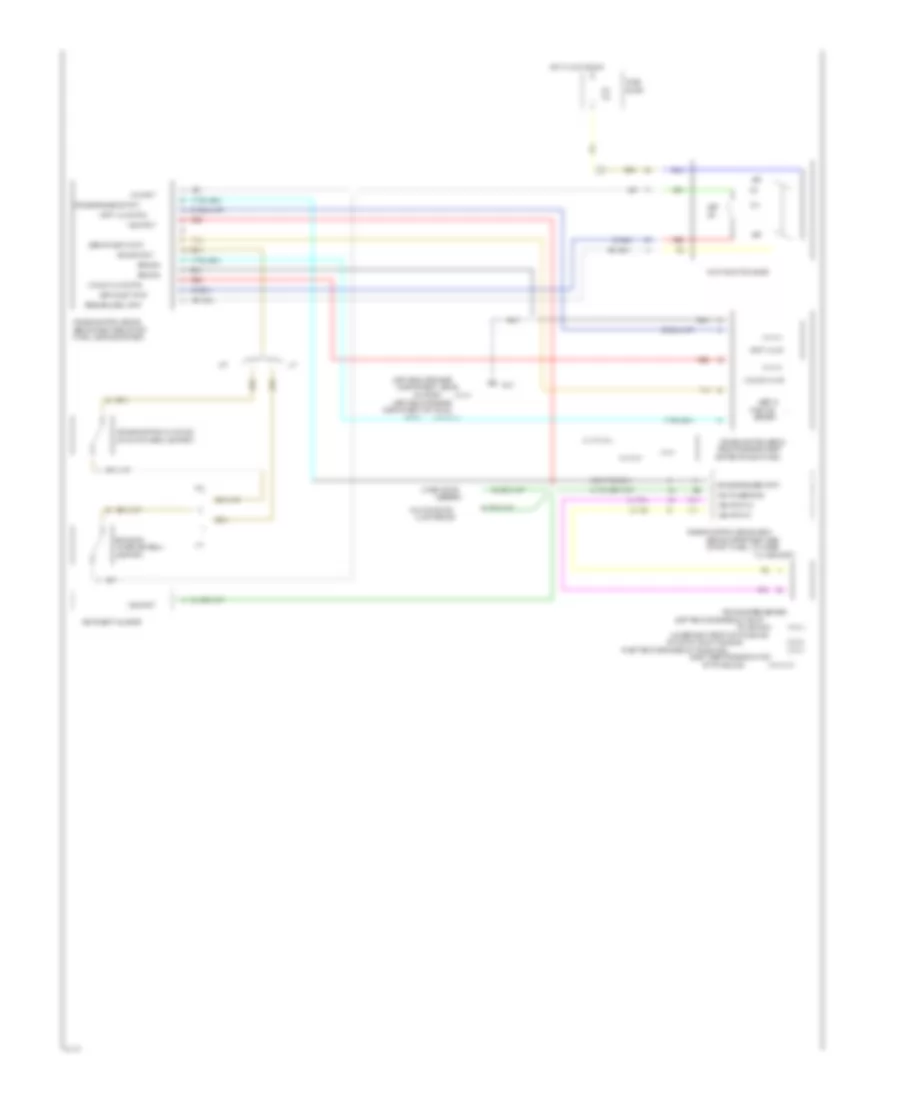
CRUISE CONTROL
Cruise Control Wiring Diagram for Chevrolet Beretta 1994
List of elements for Cruise Control Wiring Diagram for Chevrolet Beretta 1994:
- #14
- (behind right side of inst.
- (behind upper right side
- (left rear of engine
- (left rear of engine on top of
- (lower right front of transaxle
- (on brake pedal
- (on clutch pedal support)
- (rear of engine compt
- (right rear of engine on transaxle)
- (right side of engine on top
- (vin 4)
- (vin 4/a/t)
- (vin a)
- (vin m & 4)
- (vin m)
- 15a
- 4000 pulses/mile
- A/t
- Alarm module
- Assembly
- Block
- Brake input
- Brake sw
- Center of dash panel)
- Compartment on trans.
- Compartment, above
- Cruise control clutch sw
- Cruise control module
- Cruise control servo
- Cruise engage output
- Cruise engaged input
- D13
- D14
- Engine control module (ecm)
- Fuse
- G101
- Ground
- Hot in accy or run
- Instrument cluster
- L4 vin 4 & a
- M/t
- Multi/function
- Multi/function lever
- Of inst. panel, attached
- Of transaxle)
- Off
- On input
- On output shaft housing)
- Panel, above glove box)
- Position
- R/a
- Red
- Resume/accel input
- Sensor
- Servo
- Servo postn input
- Set
- Set/coast input
- Starter)
- Stud)
- Support)
- Tan
- To a bracket)
- Transaxle)
- V6 vin m
- Vacuum valve
- Vacuum valve ctrl
- Vehicle speed sensor
- Vent valve
- Vent valve ctrl
- Vss input
- Vss input/hi
- Vss input/lo
- Wiper motor
 English