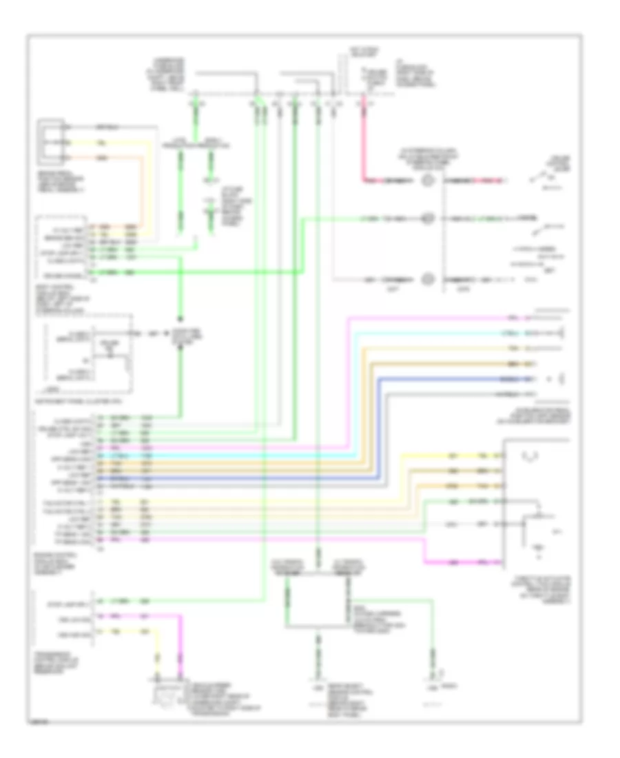
CRUISE CONTROL
Cruise Control Wiring Diagram for Chevrolet Uplander LT 2007
List of elements for Cruise Control Wiring Diagram for Chevrolet Uplander LT 2007:
- (in steering column) inflatable restraint steering wheel module coil
- 10 volt ref
- 5 volt ref 1
- 5 volt ref 2
- Accelerator pedal position (app) sensor (on accelerator bracket)
- App sens 1 sig
- App sens 2 sig
- Body control module (bcm) (below left side of dash, left of steering column)
- Brake pedal position sensor (above brake pedal assembly)
- Brake sen sig
- C277
- C279
- Cancel
- Class 2 data
- Class 2 serial data
- Computer data lines system
- Cruise cancel
- Cruise control lever
- Cruise ctrl sw sig stop lamp volt
- Cruise ind
- Cruise/ switch fuse 9 2a
- Early production
- Engine control module (ecm) (in air cleaner assembly)
- Hot in run or start
- I/p fuse block (right side of dash, behind access panel)
- Instrument panel cluster (ipc)
- Late production
- Logic
- Low ref
- Nca
- Pnk
- Radio
- Rear object sensor control module (behind right rear interior body panel)
- Res+
- S202 (in dash harness, 10.5 cm from breakout for c204 toward g200)
- Set-
- Stop lamp sply
- Tac motor ctrl 1
- Tac motor ctrl 2
- Tan
- Throttle actuator control (tac) module (rear of engine, on throttle body assembly)
- Tp sens 1 sig
- Tp sens 2 sig
- Transmission control module (behind coolant reservoir)
- Underhood fuse block (in underhood compt, above right front wheel well)
- Vehicle speed sensor (vss) (lower right rear of underhood compt, mounted to right side of transmission)
- Vss
- Vss high sig
- Vss low sig
- W/ traffic information receiver
- W/o traffic information receiver
 English