CRUISE CONTROL
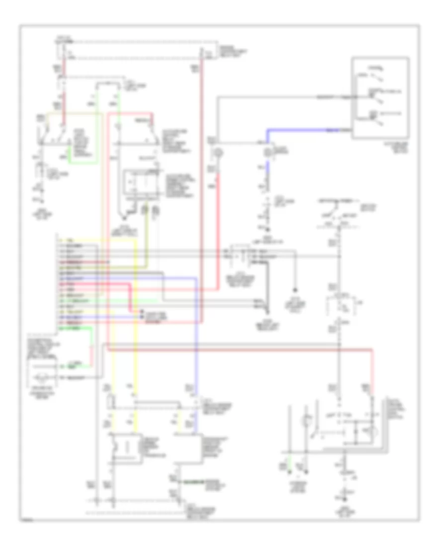
2.0L
2.0L, Cruise Control Wiring Diagram, A/T for Dodge Avenger ES 1995

List of elements for 2.0L, Cruise Control Wiring Diagram, A/T for Dodge Avenger ES 1995:
- Acc
- Acc/ res
- Auto- cruise control main switch
- Auto-cruise control relay (right rear of engine compartment)
- Auto-cruise control switch
- Auto-cruise speed control assembly (right rear of engine compartment)
- B-41
- B-54
- Cancel
- Clock spring
- Coast/ set
- Combination meter
- Computer data lines system
- Cruise ind
- Eatx-ecm (left side of engine compartment)
- Engine compartment relay box
- F1 15a
- F8 10a
- Fl3 30a
- G106 (behind left headlight)
- G116 (left side of safety wall)
- G202 (left side of i/p)
- Hot at all times
- Ignition switch
- Ill
- Ind
- Input speed sensor (on transaxle)
- Interior lights system
- J/b
- J/c 1 (left side of i/p)
- J/c 2 (left side of i/p)
- J/c 3 (below engine compartment relay box)
- J/c 4 (below engine compartment relay box)
- Nca
- Off
- Output speed sensor (on transaxle)
- Park/ neutral position switch (top of trans)
- Pnk
- Powertrain control module (forward of left front strut tower)
- Red
- Run
- Start
- Starting/ charging system
- Stop light switch (top of brake pedal support)
- Transmissions system
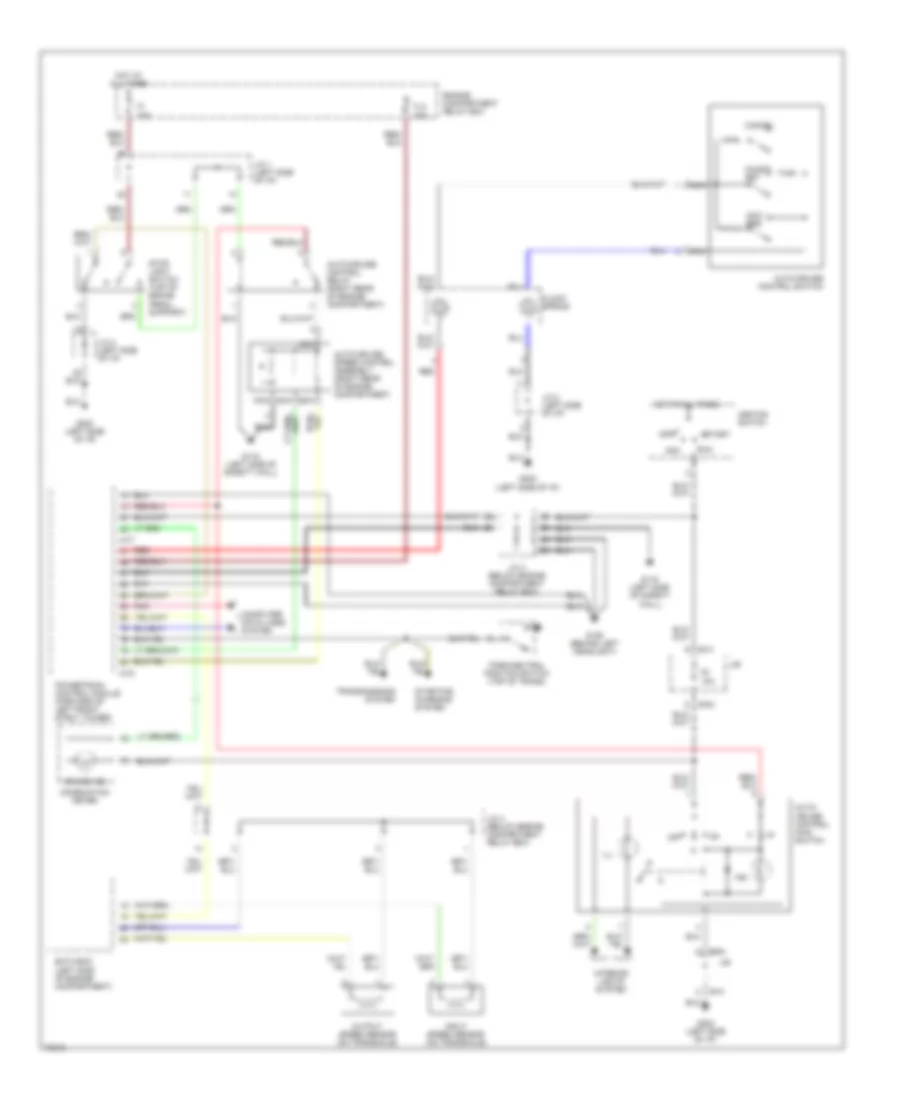
2.0L, Cruise Control Wiring Diagram, M/T for Dodge Avenger ES 1995
List of elements for 2.0L, Cruise Control Wiring Diagram, M/T for Dodge Avenger ES 1995:
- Acc
- Acc/ res
- Auto- cruise control main switch
- Auto-cruise control relay (right rear of engine compartment)
- Auto-cruise control switch
- Auto-cruise speed control assembly (right rear of engine compartment)
- B-41
- B-54
- Cancel
- Clock spring
- Coast/ set
- Combination meter
- Computer data lines system
- Crankshaft position sensor (front of engine)
- Cruise ind
- Engine compartment relay box
- Engine controls system
- F1 15a
- F8 10a
- Fl3 30a
- G106 (behind left headlight)
- G116 (left side of safety wall)
- G202 (left side of i/p)
- Hot at all times
- Ignition switch
- Ill
- Ind
- Interior lights system
- J/b
- J/c 1 (left side of i/p)
- J/c 2 (left side of i/p)
- J/c 3 (below engine compartment relay box)
- J/c 4 (below engine compartment relay box)
- Nca
- Off
- Pnk
- Powertrain control module (forward of left front strut tower)
- Red
- Run
- Start
- Stop light switch (top of brake pedal support)
- Vehicle speed sensor (on transaxle)
2.5L
2.5L, Cruise Control Wiring Diagram for Dodge Avenger ES 1995
List of elements for 2.5L, Cruise Control Wiring Diagram for Dodge Avenger ES 1995:
- A-77
- A-78
- Acc
- Acc/ res
- Auto- cruise control main switch
- Auto-cruise control relay (right rear of engine compartment)
- Auto-cruise control switch
- Auto-cruise speed control assembly (right rear of engine compartment)
- B-41
- B-54
- Cancel
- Clock spring
- Coast/ set
- Combination meter
- Computer data lines system
- Cruise ind
- Eatx-ecm (left side of engine compartment)
- Engine compartment relay box
- F1 15a
- F8 10a
- Fl3 30a
- G106 (behind left headlight)
- G116 (left side of safety wall)
- G202 (left side of i/p)
- Hot at all times
- Ignition switch
- Ill
- Ind
- Input speed sensor (on transaxle)
- Interior lights system
- J/b
- J/c 1 (left side of i/p)
- J/c 2 (left side of i/p)
- J/c 3 (below engine compartment relay box)
- J/c 4 (below engine compartment relay box)
- Nca
- Off
- Output speed sensor (on transaxle)
- Park/neutral position switch (top of trans)
- Pnk
- Powertrain control module (forward of left front strut tower)
- Red
- Run
- Start
- Starting/ charging system
- Stop light switch (top of brake pedal support)
- Transmissions system