CRUISE CONTROL
2.4L
2.4L, Cruise Control Wiring Diagram (1 of 2) for Dodge Avenger R/T 2012

List of elements for 2.4L, Cruise Control Wiring Diagram (1 of 2) for Dodge Avenger R/T 2012:
- (left rear of engine compt, in headlamp & dash harness) s129
- (left rear of engine, in engine harness) s192
- (or a909)
- (or pnk)
- (or z911)
- 5v eng snsr prim
- A209
- A929
- App sens fd 2
- App sens rtn
- App sens rtn 2
- App sig 1
- App sig 2
- B(+)
- B15
- B16
- Batt fd 9
- Brake sig 1
- Brake sig 2
- C104
- C11
- C114
- Can bus (+)
- Can bus (-)
- Can bus +
- Can bus -
- Chrysler
- Circuit board
- Computer data lines system
- Ctrl sw sig
- D507
- D64
- D65
- Dimm env lgt
- Dodge
- Exterior lights system
- F855
- Fuse 10a
- Fused b(+)
- G309 (left side of engine compt)
- Gnd
- Horn switch
- Hot at all times
- Hot in on or start
- Hrn sw sig
- Input spd sig
- K122
- K124
- K126
- K167
- K22
- K23
- K29
- K400
- K852
- K854
- K922
- L53
- Left radio remote switch
- Left steering wheel switch
- Lin sccm
- Mtr pos ctrl
- Nca
- Out spd sig
- Pos snse fd 1
- Powertrain control module
- Red
- Right radio remote switch
- Rmux rtn
- Rmux sig 1
- S103c
- S160
- S2003 (chrysler) s461 (dodge)
- Snse rtn
- Spd ctrl rtn
- Spd ctrl sens 2
- Spd ctrl snse 1
- Spd ctrl snse 2
- Spd snse rtn
- Speed control switch (chrysler) right steering wheel switch (dodge)
- Steering control module (steering column)
- Stop lamp fd cmbd
- Sw sens rtn
- T13
- T14
- T52
- T85
- Totally integrated power module (left side of engine compt)
- Tp sens rtn
- Tp sig 1
- Tp sig 2
- Trans spd sig
- V71
- V72
- V937
- Z902
- Z910
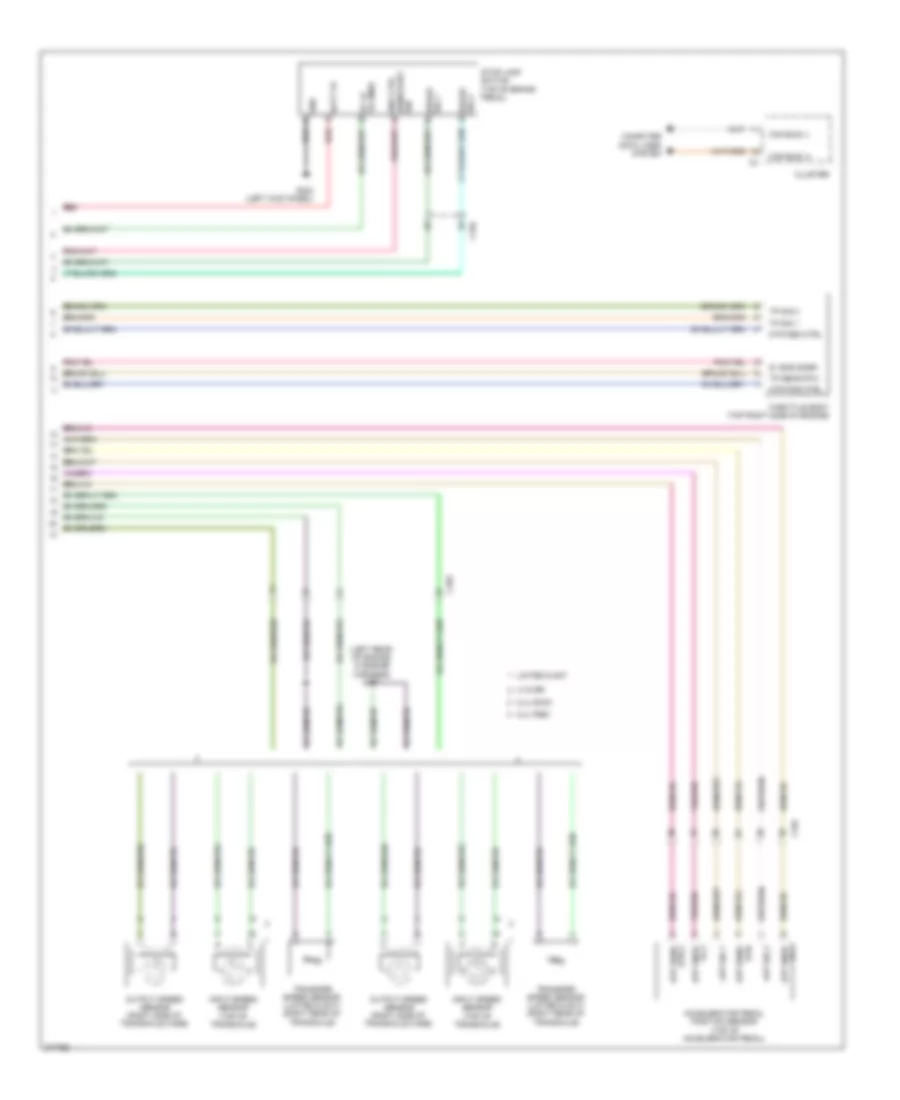
2.4L, Cruise Control Wiring Diagram (2 of 2) for Dodge Avenger R/T 2012
List of elements for 2.4L, Cruise Control Wiring Diagram (2 of 2) for Dodge Avenger R/T 2012:
- (left rear of engine, in engine harness) s107
- 2.4l dohc
- 2.4l pzev
- 5v eng snsr
- Accelerator pedal position sensor (top of accelerator pedal)
- App sens rtn 2
- App sig 1
- App sig 2
- App snse fd 1
- App snse fd 2
- Batt fd red
- Brake sig 1
- Brake sig 2
- C103
- C104
- Can bus (+)
- Can bus (-)
- Cluster
- Computer data lines system
- G302 (left kick panel)
- Gnd
- Ign
- Input speed sensor (top of transaxle)
- Limited & sxt
- Lx & se
- Mtr pos ctrl
- Output speed sensor (right side of transaxle case)
- Red
- Rtn app sens
- St lp fd cmbd
- Stop lamp switch (top of brake pedal)
- Throttle body (top right side of engine)
- Tp sens rtn
- Tp sig 1
- Tp sig 2
- Transfer speed sensor (limited & sxt) (right rear of transaxle)
3.6L
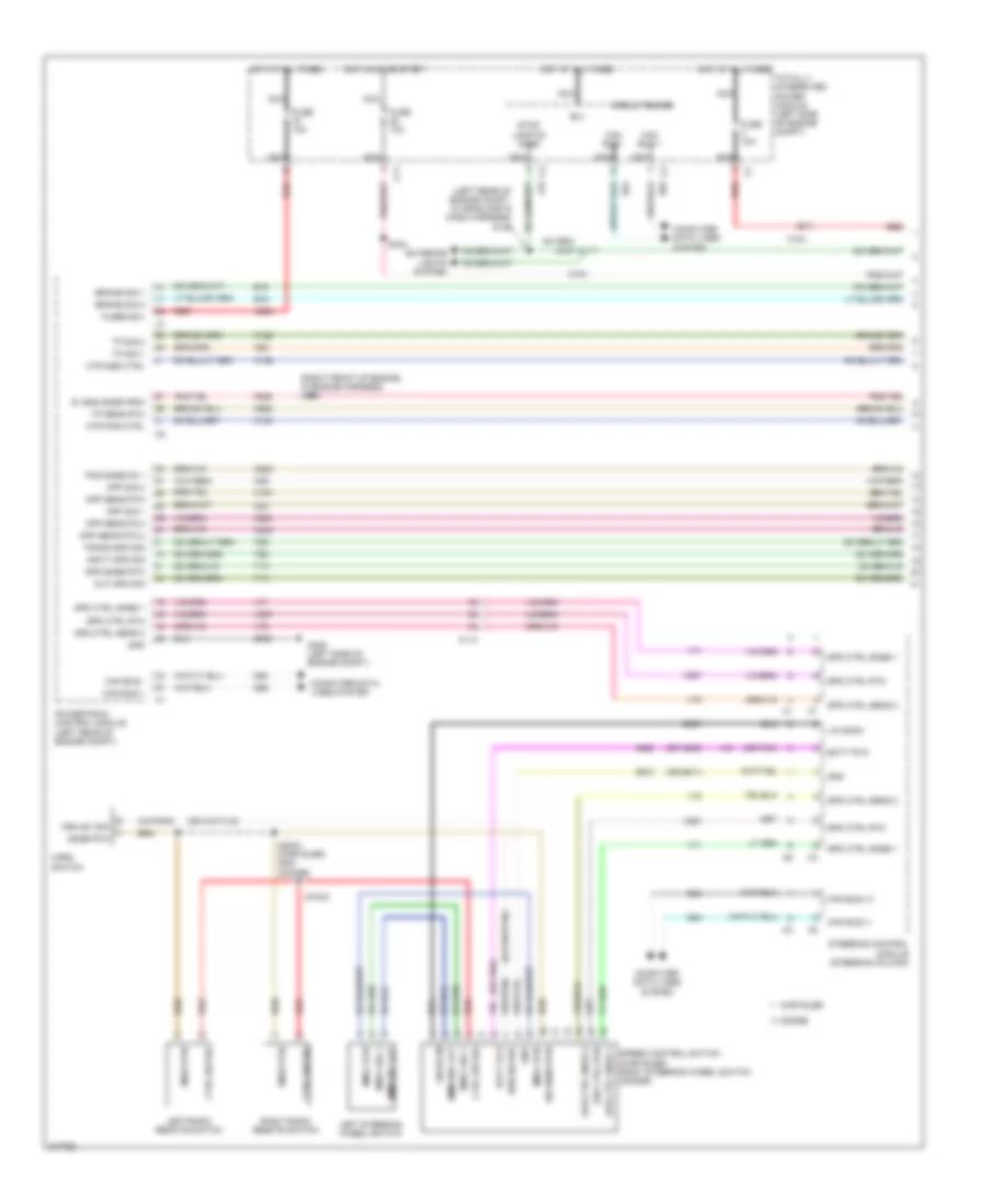
3.6L, Cruise Control Wiring Diagram (1 of 2) for Dodge Avenger R/T 2012
List of elements for 3.6L, Cruise Control Wiring Diagram (1 of 2) for Dodge Avenger R/T 2012:
- (left rear of engine compt, in headlamp & dash harness) s129
- (or a909)
- (or pnk)
- (or z911)
- (right front of engine, in engine harness) s105
- 5v eng snsr prim
- A209
- A929
- App sens fd 2
- App sens rtn
- App sens rtn 2
- App sig 1
- App sig 2
- B(+)
- B15
- B16
- Batt fd 9
- Brake sig 1
- Brake sig 2
- C104
- C11
- C114
- Can bus (+)
- Can bus (-)
- Can bus +
- Can bus -
- Chrysler
- Circuit board
- Computer data lines system
- Ctrl sw sig
- D507
- D64
- D65
- Dimm env lgt
- Dodge
- Exterior lights system
- F855
- Fuse 10a
- Fused b(+)
- G309 (left side of engine compt)
- Gnd
- Horn switch
- Hot at all times
- Hot in on or start
- Hrn sw sig
- Input spd sig
- K122
- K124
- K126
- K167
- K22
- K23
- K29
- K400
- K852
- K854
- K922
- L53
- Left radio remote switch
- Left steering wheel switch
- Lin sccm
- Mtr pos ctrl
- Nca
- Out spd sig
- Pos snse fd 1
- Powertrain control module (left rear of engine compt)
- Red
- Right radio remote switch
- Rmux rtn
- Rmux sig 1
- S103c
- S160
- S2003 (chrysler) s461 (dodge)
- Snse rtn
- Spd ctrl rtn
- Spd ctrl sens 2
- Spd ctrl snse 1
- Spd ctrl snse 2
- Spd snse rtn
- Speed control switch (chrysler) right steering wheel switch (dodge)
- Steering control module (steering column)
- Stop lamp fd cmbd
- Sw sens rtn
- T13
- T14
- T52
- T85
- Totally integrated power module (left side of engine compt)
- Tp sens rtn
- Tp sig 1
- Tp sig 2
- Trans spd sig
- V71
- V72
- V937
- Z902
- Z910
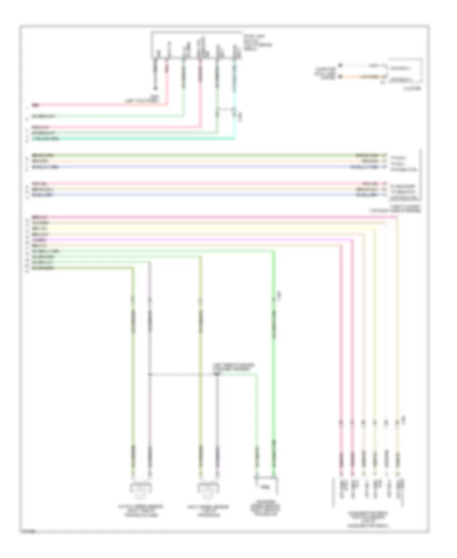
3.6L, Cruise Control Wiring Diagram (2 of 2) for Dodge Avenger R/T 2012
List of elements for 3.6L, Cruise Control Wiring Diagram (2 of 2) for Dodge Avenger R/T 2012:
- (left rear of engine, in engine harness) s107
- 5v eng snsr
- Accelerator pedal position sensor (top of accelerator pedal)
- App sens rtn 2
- App sig 1
- App sig 2
- App snse fd 1
- App snse fd 2
- Batt fd red
- Brake sig 1
- Brake sig 2
- C103
- C104
- Can bus (+)
- Can bus (-)
- Cluster
- Computer data lines system
- G302 (left kick panel)
- Gnd
- Ign
- Input speed sensor (top of transaxle)
- Mtr pos ctrl
- Output speed sensor (right side of transaxle case)
- Red
- Rtn app sens
- St lp fd cmbd
- Stop lamp switch (top of brake pedal)
- Throttle body (top right side of engine)
- Tp sens rtn
- Tp sig 1
- Tp sig 2
- Transfer speed sensor (right rear of transaxle)