CRUISE CONTROL
Cruise Control Wiring Diagram (1 of 2) for Dodge Avenger SE 2014

List of elements for Cruise Control Wiring Diagram (1 of 2) for Dodge Avenger SE 2014:
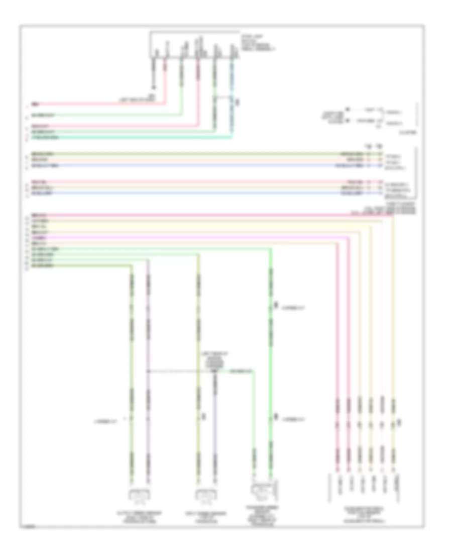
Cruise Control Wiring Diagram (2 of 2) for Dodge Avenger SE 2014
List of elements for Cruise Control Wiring Diagram (2 of 2) for Dodge Avenger SE 2014: