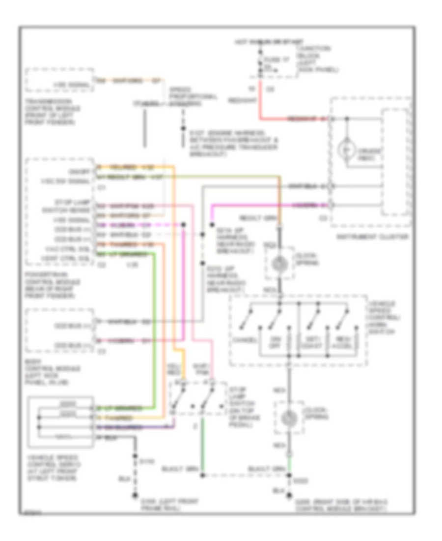
CRUISE CONTROL
Cruise Control Wiring Diagram for Dodge Intrepid 1997
List of elements for Cruise Control Wiring Diagram for Dodge Intrepid 1997:
- (engine harness,
- (i/p
- (left front
- (right side of air bag
- Body control module (left kick panel, in j/b)
- Cancel
- Ccd bus (+)
- Clock- spring
- Cruise indic.
- Fuse 17 5a
- G100 frame rail)
- G206 control module bracket)
- Hot in run or start
- Instrument cluster
- Junction block (left kick panel)
- K29
- Nca
- On/ off
- On/off
- Others
- Powertrain control module (rear of right front fender)
- Res/ accel
- S110
- S127 between fan breakout & a/c pressure tranducer breakout)
- S212 harness, near radio breakout)
- S214 harness, near radio breakout)
- S222
- Set/ coast
- Speed proportional steering
- Stop lamp
- Stop lamp switch (on top of brake pedal)
- Switch sense
- Tan/red
- Transmission control module (front of left front fender)
- V32
- V35
- V36
- V37
- Vac ctrl sol
- Vehicle speed control servo (at left front strut tower)
- Vehicle speed control/ horn switch
- Vent ctrl sol
- Vsc sw signal
- Vss signal
 English