CRUISE CONTROL
5.4L
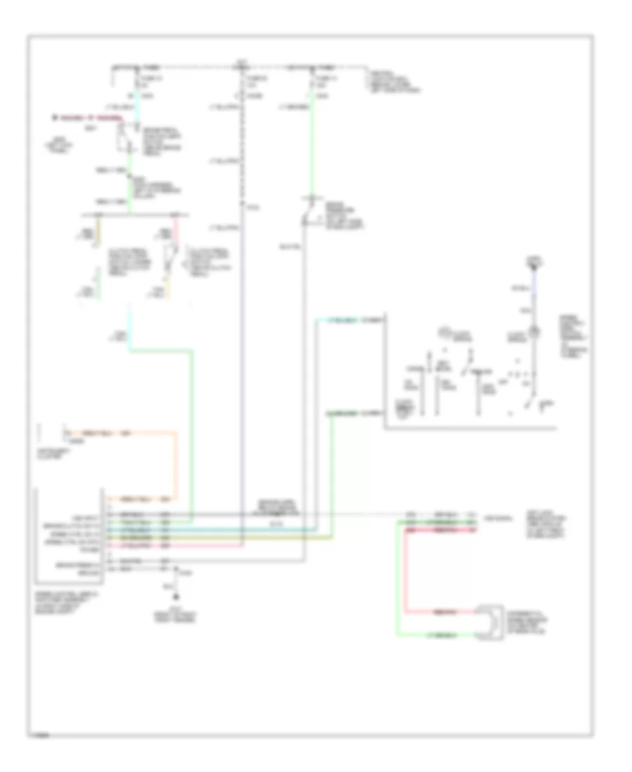
5.4L, Cruise Control Wiring Diagram for Ford Cab & Chassis F350 Super Duty 2001

List of elements for 5.4L, Cruise Control Wiring Diagram for Ford Cab & Chassis F350 Super Duty 2001:
- (engine harn, below brake fluid reservoir)
- 10a
- 20a
- A/t
- Accel
- Anti-lock brake system (abs) module (in left front of eng compt)
- Brake pedal position (bpp) switch (above brake pedal)
- Brake press in
- Brake pressure switch (on left side of eng compt)
- Brake/clutch sw in
- C242
- C242b
- C243
- C250b
- Central junction box (behind lower left side of dash)
- Clock spring
- Clutch pedal position (cpp) switch (above clutch pedal)
- Clutch pedal position (cpp) switch jumper (above clutch pedal)
- Coast
- Differential speed sensor (on center of rear axle)
- Fuse 13
- Fuse 15
- Fuse 28
- G101 (front of right front fender)
- G200 (left kick panel)
- Ground
- Horn
- Horn relay
- Hot at all times
- Hot in run
- Instrument cluster
- M/t
- Nca
- Off
- Ohms
- Power
- Red/pnk
- Resume
- S115
- S124
- S180
- S201
- S205 (main harness, left of steering column)
- Set/
- Speed control servo/ amplifier assembly (in right side of engine compt)
- Speed control/ horn switch assembly (in steering wheel)
- Speed ctrl sw in
- Speed ctrl sw rtn
- Vss input
- Vss signal
6.8L
6.8L, Cruise Control Wiring Diagram for Ford Cab & Chassis F350 Super Duty 2001
List of elements for 6.8L, Cruise Control Wiring Diagram for Ford Cab & Chassis F350 Super Duty 2001:
- (engine harn, below brake fluid reservoir)
- 10a
- 20a
- A/t
- Accel
- Anti-lock brake system (abs) module (in left front of eng compt)
- Brake pedal position (bpp) switch (above brake pedal)
- Brake press in
- Brake pressure switch (on left side of eng compt)
- Brake/clutch sw in
- C242
- C242b
- C243
- C250b
- Central junction box (behind lower left side of dash)
- Clock spring
- Clutch pedal position (cpp) switch (above clutch pedal)
- Clutch pedal position (cpp) switch jumper (above clutch pedal)
- Coast
- Differential speed sensor (on center of rear axle)
- Fuse 13
- Fuse 15
- Fuse 28
- G101 (front of right front fender)
- G200 (left kick panel)
- Ground
- Horn
- Horn relay
- Hot at all times
- Hot in run
- Instrument cluster
- M/t
- Nca
- Off
- Ohms
- Power
- Red/pnk
- Resume
- S115
- S124
- S180
- S201
- S205 (main harness, left of steering column)
- Set/
- Speed control servo/ amplifier assembly (in right side of engine compt)
- Speed control/ horn switch assembly (in steering wheel)
- Speed ctrl sw in
- Speed ctrl sw rtn
- Vss input
- Vss signal
7.3L DI TURBO DIESEL
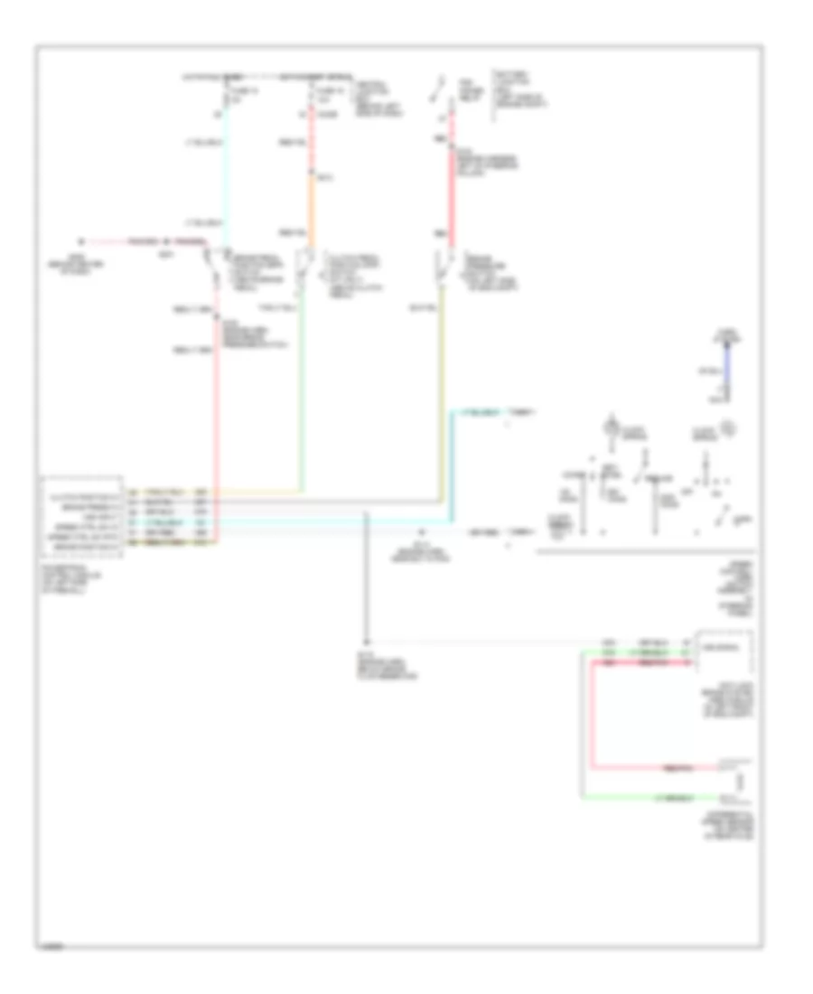
7.3L DI Turbo Diesel, Cruise Control Wiring Diagram for Ford Cab & Chassis F350 Super Duty 2001
List of elements for 7.3L DI Turbo Diesel, Cruise Control Wiring Diagram for Ford Cab & Chassis F350 Super Duty 2001:
- 10a
- Accel
- Anti-lock brake system (abs) module (in left front of eng compt)
- Battery junction box (left side of engine compt)
- Brake pedal position (bpp) switch (above brake pedal)
- Brake position in
- Brake press in
- Brake pressure switch (on left side of eng compt)
- C242b
- Central junction box (behind left side of dash)
- Clock spring
- Clutch pedal position (cpp) switch (m/t only) (above clutch pedal)
- Clutch position in
- Coast
- Differential speed sensor (on center of rear axle)
- Fuse 15
- Fuse 19
- G206 (behind center of dash)
- Horn
- Horn system
- Hot at all times
- Hot in start or run
- Nca
- Off
- Ohms
- Pcm power relay
- Powertrain control module (on left side of firewall)
- Red
- Red/pnk
- Resume
- S108 (engine harn, near brake pressure switch)
- S114 (engine harn, near b/o to pcm)
- S115 (engine harn, below brake fluid reservoir)
- S123 (engine harness, left of steering column)
- S201
- S213
- Set/
- Speed control/ horn switch assembly (in steering wheel)
- Speed ctrl sw in
- Speed ctrl sw rtn
- Vss input
- Vss signal