CRUISE CONTROL
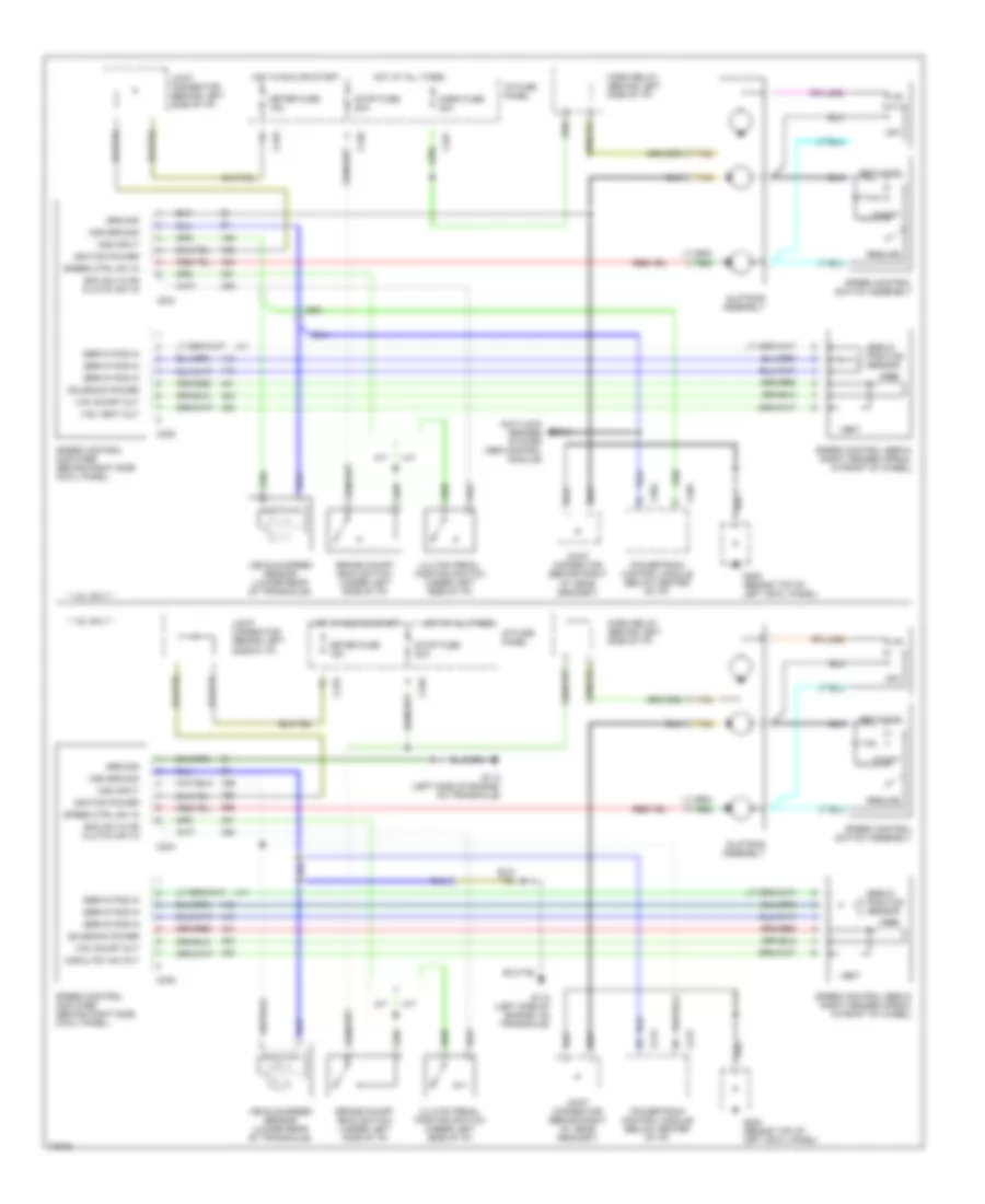
Cruise Control Wiring Diagram for Ford Escort 1996
List of elements for Cruise Control Wiring Diagram for Ford Escort 1996:
- * 1.8l only *
- * 1.9l only *
- A/t
- Anti-lock brakes system (abs control module)
- Boo sw in or clutch sw in
- Brake on/off (boo) switch (under left side of i/p)
- C204
- C210
- C212
- C227
- C234
- C235
- C240
- Clutch pedal position switch (under left side of i/p)
- Coast
- G112 (left side of engine, on transaxle)
- G200 (behind top of left cowl panel)
- Ground
- Horn fuse 20a
- Horn relay (behind left side of i/p)
- Hot at all times
- Hot in run or start
- I/p fuse panel
- Ignition power
- Joint connector (behind left side of i/p)
- Joint connector (behind right i/p, near grommet)
- M/t
- Meter fuse 15a
- Modulte vac out
- Off
- Powertrain control module (below center of i/p)
- Resume
- Servo pos in
- Servo position sensor
- Set/accel
- Slip ring assembly
- Solenoid power
- Speed control amplifier (behind right side cowl panel)
- Speed control servo (right fender apron, in front of wheel)
- Speed control switch assembly
- Speed ctrl sw in
- Stop fuse 20a
- Tan
- Vac
- Vac on/off out
- Vac vent out
- Vehicle speed sensor (lower rear of transaxle)
- Vent
- Vss ground
- Vss input
 English