CRUISE CONTROL
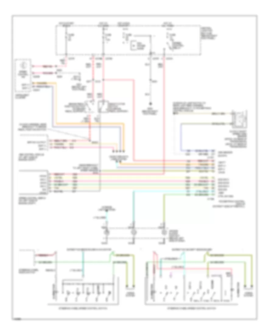
Cruise Control Wiring Diagram for Ford Expedition 2004
List of elements for Cruise Control Wiring Diagram for Ford Expedition 2004:
- (in back-up lamp switch to rear lamp feed harness, near breakout to powertrain control module) s138
- (in main harness, near breakout to brake pedal position switch)
- (near breakout to left front wheel speed sensor) s103
- Abs control module (at left side of engine compt)
- Air bag sliding contact (behind left side of dash)
- Bpp sw output
- Brake pedal position switch (on brake pedal support)
- C175b
- C175t
- C220a
- C220b
- C270a
- C270b
- C270e
- C270f
- Central junction box (cjb) (behind right kick panel)
- Computer data lines system
- Ctrl sw gnd
- Deactivator switch (on brake pedal support)
- Expedition (except eddie bauer)
- Expedition eddie bauer & navigator
- Fuse 10a
- Fuse 5a
- Fuse 7.5a
- G200 (behind right kick panel)
- G301 (behind left kick panel)
- Horns system
- Hot at all times
- Hot in run or start
- Hot in start or run
- Illumination
- Instrument cluster
- Interior lights system
- Nca
- Off
- Oss sensor
- Output shaft speed (oss) sensor (4r70w: on rear of transmission) (4r100: at rear of transmission)
- Pcm power diode
- Powertrain control module (on right side of firewall)
- Resume
- S133
- S2003
- S203
- S208
- S277
- S282
- Scp (+)
- Scp (-)
- Scs sig
- Scs sig a
- Scs sig b
- Scs sig c
- Set (+)
- Set (-)
- Sig
- Sig a
- Sig b
- Sig c
- Sig rtn
- Speed control ind
- Speed control relay
- Speed control servo (on left side of engine compt)
- Steering wheel radio switch
- Steering wheel/speed control switch
- Tan
- Vbatt
- Vpwr
- Vref
 English