CRUISE CONTROL
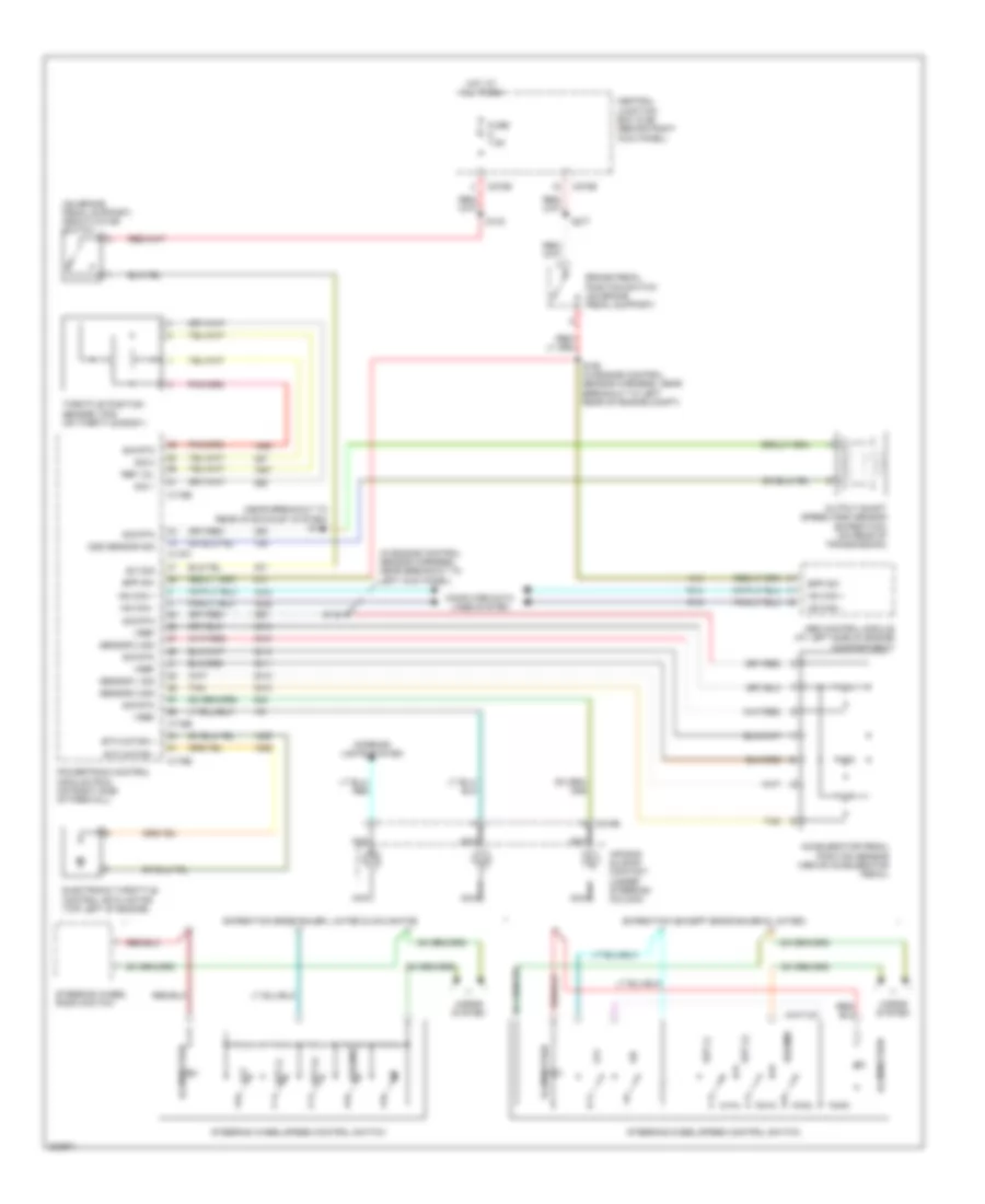
Cruise Control Wiring Diagram for Ford Expedition 2006
List of elements for Cruise Control Wiring Diagram for Ford Expedition 2006:
- (in engine control sensor harness, near breakout to left kick panel)
- (near breakout to rear of exhaust system) s141
- (on brake pedal support) deactivator switch
- Abs control module (at left side of engine compartment)
- Accelerator pedal position sensor (above accelerator pedal)
- Air bag sliding contact (under steering column)
- Bpp sw
- Brake pedal position switch (on brake pedal support)
- C175b
- C175e
- C175t
- C218b
- C270b
- C270e
- Central junction box (cjb) (behind right kick panel)
- Computer data lines system
- Electronic throttle control (etc) motor (top left of engine)
- Etc motor +
- Etc motor -
- Expedition (except eddie bauer & limited)
- Expedition eddie bauer, limited & navigator
- Fuse 7.5a
- Horns system
- Hot at all times
- Hs can +
- Hs can -
- Illumination
- Interior lights system
- Nca
- Off
- Oss sensor sig
- Output shaft speed (oss) sensor (expedition) (on rear of transmission)
- Powertrain control module (pcm) (on right side of firewall)
- Ref vol
- Resume
- S133
- S148
- S150 (in engine control sensor harness, near breakout to left rear of engine compt)
- S277
- Sensor 1 sig
- Sensor 2 sig
- Sensor 3 sig
- Set (+)
- Set (-)
- Sig 1
- Sig 2
- Sig rtn
- Steering wheel radio switch
- Steering wheel/speed control switch
- Sw sig
- Tan
- Throttle position sensor (tps) (on throttle body)
- Vref
 English