CRUISE CONTROL
Cruise Control Wiring Diagram for Ford Explorer 1995
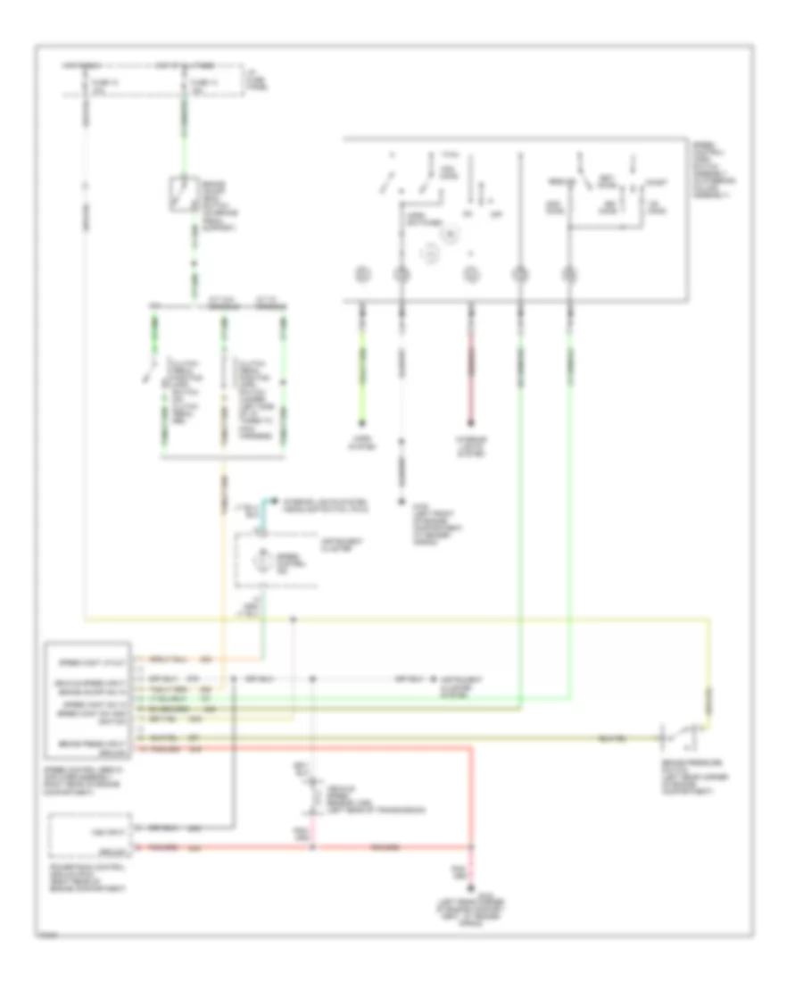
List of elements for Cruise Control Wiring Diagram for Ford Explorer 1995:
- (left rear corner of engine compart- ment, at fender apron)
- 10a
- 15a
- A/t w/ console
- A/t w/o console
- Accel
- Brake on/off (boo) switch (on brake pedal support)
- Brake on/off sw in
- Brake press input
- Brake pressure switch (left rear corner of engine compartment)
- Clutch pedal position (cpp) switch (on clutch pedal arm)
- Clutch pedal position (cpp) switch jumper (left side of i/p, taped to main harness)
- Coast
- Fuse 10
- Fuse 13
- G100 (left front of engine compartment, at fender apron)
- G104
- Ground
- Horn switches
- Horn system
- Hot at all times
- Hot in run
- I/p fuse panel
- Ignition
- Instrument cluster
- Instrument cluster system
- Interior lights system
- Interior lights system (headlamp switch, pin 8)
- M/t
- Nca
- Off
- Ohms
- Powertrain control module (pcm) (right rear of engine compartment)
- Resume
- Set/
- Speed cont lp out
- Speed cont sw gnd
- Speed cont sw in
- Speed control ind
- Speed control servo/ amplifier assembly (right rear of engine compartment)
- Speed control/ horn switch assembly (in steering column assembly)
- Vehicle speed input
- Vehicle speed sensor (vss) (left rear of transmission)
- Vss input
 English