CRUISE CONTROL
Cruise Control Wiring Diagram, with IVD for Ford Explorer 2005

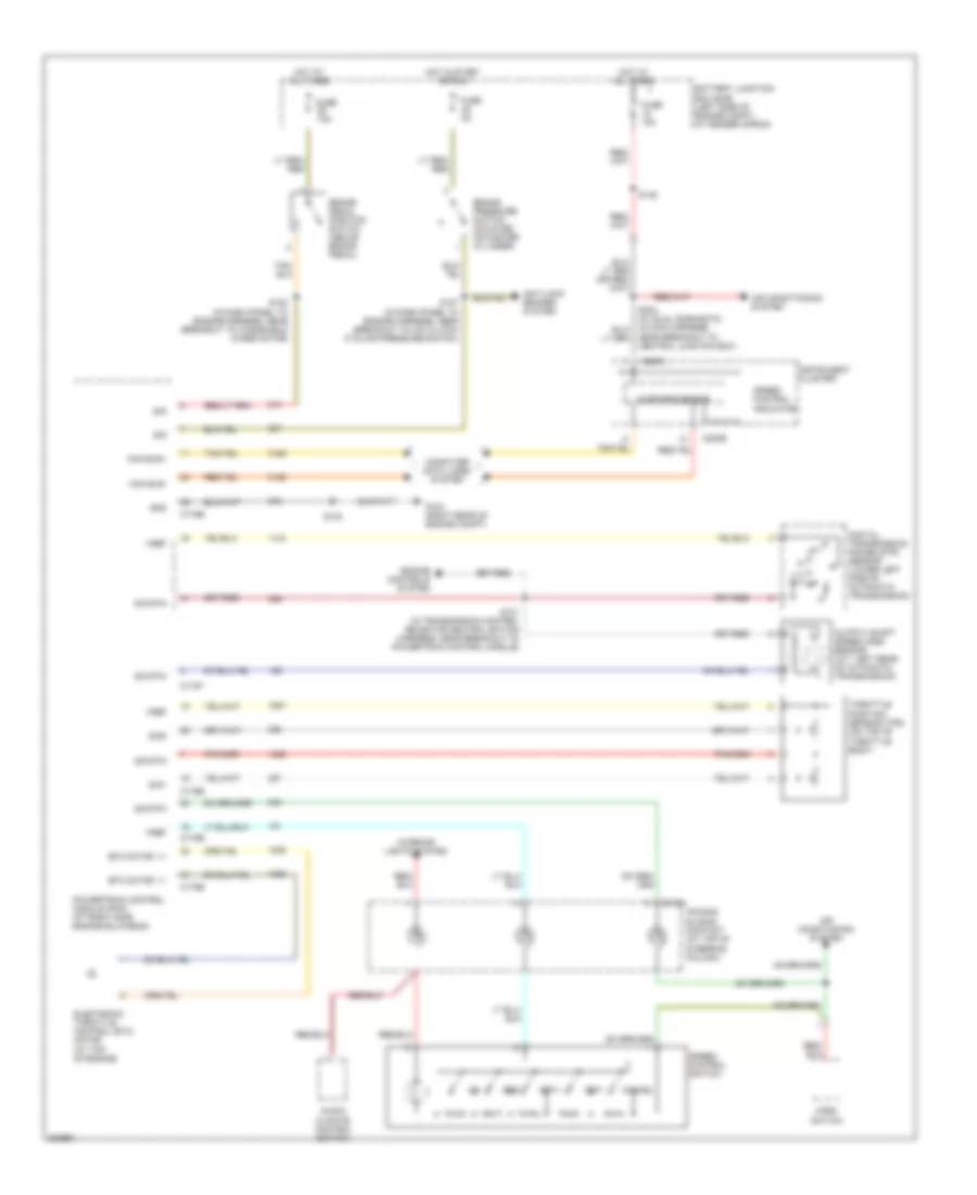
List of elements for Cruise Control Wiring Diagram, with IVD for Ford Explorer 2005:
- Air bag sliding contact (at top of steering column)
- Air conditioning system
- Audio/ climate control switch
- Battery junction box (bjb) (left side of engine compt, at fender apron)
- Brake pedal position switch (above brake pedal)
- C175b
- C175e
- C175t
- C218a
- C220a
- C220b
- Can bus+
- Can bus-
- Cancel
- Computer data lines system
- Digital transmission range (dtr) sensor (lower left side of automatic transmission)
- Electronic throttle control (etc) motor (at top of engine)
- Engine controls system
- Etc motor, +/-
- Fuse 15a
- G104 (right rear of engine compt)
- Gnd
- Horn switch
- Hot at all times
- Instrument cluster
- Interior lights system
- Microprocessor
- Near breakout to central junction box)
- Output shaft speed (oss) sensor (a/t: left rear of automatic transmission)
- Powertrain control module (pcm) (at right side engine bulkhead)
- Redundant pedal switch (under left side dash panel)
- Res
- S101 (in transmission control selector neutral switch harness, near breakout to powertrain control module)
- S120 (in dash panel to engine harness, near breakout to left horn)
- S132
- S149
- S171
- S173
- Set+
- Set-
- Sig
- Sig rtn
- Sig1
- Sig2
- Speed control indicator
- Speed control switch
- Throttle position sensor (tps) (on top of throttle body)
- Vref
Cruise Control Wiring Diagram, without IVD for Ford Explorer 2005
List of elements for Cruise Control Wiring Diagram, without IVD for Ford Explorer 2005:
- Air bag sliding contact (at top of steering column)
- Air conditioning system
- Anti-lock brakes system
- Audio/ climate control switch
- Battery junction box (bjb) (left side of engine compt, at fender apron)
- Brake pedal position switch (above brake pedal)
- Brake pressure switch (mounted on master cylinder)
- C175b
- C175e
- C175t
- C218a
- C220a
- C220b
- Can bus+
- Can bus-
- Cancel
- Computer data lines system
- Digital transmission range (dtr) sensor (lower left side of automatic transmission)
- Electronic throttle control (etc) motor (at top of engine)
- Engine controls system
- Etc motor, +/-
- Fuse 15a
- Fuse 2a
- G104 (right rear of engine compt)
- Gnd
- Horn switch
- Hot at all times
- Hot in start or run
- Instrument cluster
- Interior lights system
- Microprocessor
- Near breakout to central junction box)
- Output shaft speed (oss) sensor (a/t: left rear of automatic transmission)
- Powertrain control module (pcm) (at right side engine bulkhead)
- Res
- S101 (in transmission control selector neutral switch harness, near breakout to powertrain control module)
- S120 (in dash panel to engine harness, near breakout to windshield wiper motor)
- S127 (in dash panel to engine harness, near breakout to a/c clutch cycling pressure switch)
- S132
- S149
- Set+
- Set-
- Sig
- Sig rtn
- Sig1
- Sig2
- Speed control indicator
- Speed control switch
- Throttle position sensor (tps) (on top of throttle body)
- Vref