CRUISE CONTROL
4.2L
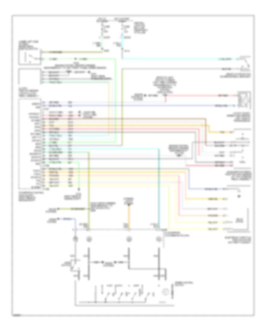
4.2L, Cruise Control Wiring Diagram for Ford Pickup F350 Super Duty 2008

List of elements for 4.2L, Cruise Control Wiring Diagram for Ford Pickup F350 Super Duty 2008:
- (back-up light switch to rear light feed harness, near breakout to powertrain control module (pcm)) s141
- (engine control sensor harness, near breakout to c139) s104
- (main wiring harness, near breakout to ignition switch) s296
- (under left side of dash) brake pedal position switch
- Acceleration pedal position (app) sensor (at top of brake pedal assembly)
- App1
- App2
- App3
- Boo
- Bps
- C175b
- C175e
- C175t
- C218b
- C270b
- C270f
- Can bus +
- Can bus -
- Central junction box (cjb) (near right "a" pillar)
- Clockspring (in steering column)
- Clutch position sensor (top of clutch pedal assembly)
- Coast
- Computer data lines system
- Cpp bt
- Cpp tt
- Deactivator switch (on brake pedal bracket)
- Electronic throttle position motor (on throttle body)
- Engine controls system
- Etc ref
- Etcref
- Etcrtn
- Fuse 10a
- Fuse 20a
- G102 (right rear of engine compt)
- G103 (right rear of engine compt)
- Gnd
- Horn switch
- Horns system
- Hot at all times
- Hot in start or run
- Illumination
- Interior lights system
- Nca
- Off
- Oss
- Output shaft speed (oss) sensor (left side of transmission)
- Powertrain control module (pcm) (right rear of engine compt)
- S102
- S109 (engine control sensor harness, near breakout to left front wheel speed sensor)
- S112
- S220
- Sccs
- Sccsrtn
- Set
- Sig rtn
- Sigrtn
- Solid state
- Sound systems
- Speed control switch
- Tacm+
- Tacm-
- Tan
- Tp1
- Tp2
4.6L
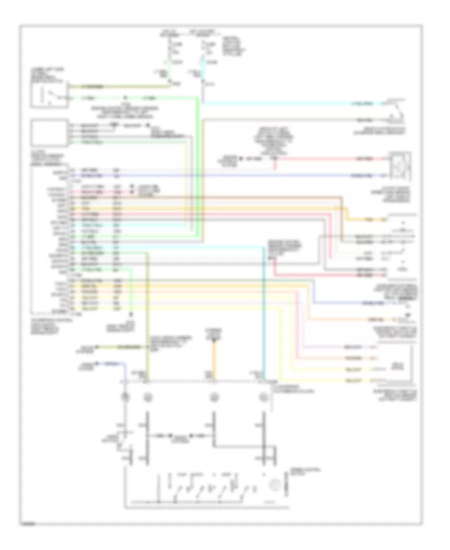
4.6L, Cruise Control Wiring Diagram for Ford Pickup F350 Super Duty 2008
List of elements for 4.6L, Cruise Control Wiring Diagram for Ford Pickup F350 Super Duty 2008:
- (back-up light switch to rear light feed harness, near breakout to powertrain control module (pcm)) s141
- (engine control sensor harness, near breakout to c139) s104
- (main wiring harness, near breakout to ignition switch) s296
- (under left side of dash) brake pedal position switch
- Acceleration pedal position (app) sensor (at top of brake pedal assembly)
- App1
- App2
- App3
- Boo
- Bps
- C175b
- C175e
- C175t
- C218b
- C270b
- C270f
- Can bus +
- Can bus -
- Central junction box (cjb) (near right "a" pillar)
- Clockspring (in steering column)
- Clutch position sensor (top of clutch pedal assembly)
- Coast
- Computer data lines system
- Cpp bt
- Cpp tt
- Deactivator switch (on brake pedal bracket)
- Electronic throttle position motor (on throttle body)
- Engine controls system
- Etc ref
- Etcref
- Etcrtn
- Fuse 10a
- Fuse 20a
- G102 (right rear of engine compt)
- G103 (right rear of engine compt)
- Gnd
- Horn switch
- Horns system
- Hot at all times
- Hot in start or run
- Illumination
- Interior lights system
- Nca
- Off
- Oss
- Output shaft speed (oss) sensor (left side of transmission)
- Powertrain control module (pcm) (right rear of engine compt)
- S102
- S109 (engine control sensor harness, near breakout to left front wheel speed sensor)
- S112
- S220
- Sccs
- Sccsrtn
- Set
- Sig rtn
- Sigrtn
- Solid state
- Sound systems
- Speed control switch
- Tacm+
- Tacm-
- Tan
- Tp1
- Tp2
5.4L
5.4L, Cruise Control Wiring Diagram for Ford Pickup F350 Super Duty 2008
List of elements for 5.4L, Cruise Control Wiring Diagram for Ford Pickup F350 Super Duty 2008:
- (back-up light switch to rear light feed harness, near breakout to powertrain control module (pcm)) s141
- (engine control sensor harness, near breakout to c139) s104
- (main wiring harness, near breakout to ignition switch) s296
- (under left side of dash) brake pedal position switch
- Acceleration pedal position (app) sensor (at top of brake pedal assembly)
- App1
- App2
- App3
- Boo
- Bps
- C175b
- C175e
- C175t
- C218b
- C270b
- C270f
- Can bus +
- Can bus -
- Central junction box (cjb) (near right "a" pillar)
- Clockspring (in steering column)
- Clutch position sensor (top of clutch pedal assembly)
- Coast
- Computer data lines system
- Cpp bt
- Cpp tt
- Deactivator switch (on brake pedal bracket)
- Electronic throttle control (etc) motor (on throttle body)
- Electronic throttle position sensor (on throttle body)
- Engine controls system
- Etc ref
- Etcref
- Etcrtn
- Fuse 10a
- Fuse 20a
- G102 (right rear of engine compt)
- G103 (right rear of engine compt)
- Gnd
- Horn switch
- Horns system
- Hot at all times
- Hot in start or run
- Illumination
- Interior lights system
- Nca
- Off
- Oss
- Output shaft speed (oss) sensor (left side of transmission)
- Powertrain control module (pcm) (right rear of engine compt)
- S102
- S109 (engine control sensor harness, near breakout to left front wheel speed sensor)
- S112
- S220
- Sccs
- Sccsrtn
- Set
- Sig rtn
- Sigrtn
- Solid state
- Sound systems
- Speed control switch
- Tacm+
- Tacm-
- Tan
- Tp1
- Tp2