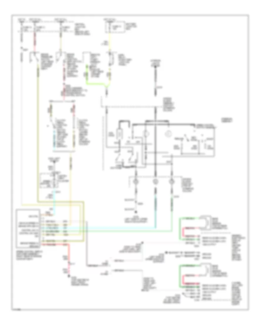
CRUISE CONTROL
Cruise Control Wiring Diagram for Ford Ranger 2000
List of elements for Cruise Control Wiring Diagram for Ford Ranger 2000:
- (dash to headlamp harn, left side of eng compt) s139
- 20a
- 4 wheel anti-lock brake system (4wabs) module (on left front of engine compt)
- 7.5a
- A/t
- Accel
- Air bag sliding assembly contact (steering column)
- Air bag sliding contact (top of steering column)
- Battery junction box
- Brake pedal position (bpp) switch (behind left side of dash, on brake pedal support)
- Brake press in
- Brake pressure switch (left rear of engine compart- ment)
- C154
- C214
- C219
- C221
- C224
- C409
- Central junction box (behind left side of dash)
- Clutch pedal position (cpp) switch (behind left side of dash, top of clutch pedal support)
- Clutch pedal position (cpp) switch jumper (behind dash, left of steering column)
- Coast
- Control sw gnd
- Control sw in
- Fuse 10
- Fuse 10 15a
- Fuse 13
- Fuse 9
- G104 (top center of left front fender apron)
- G105 (top center of right front fender apron)
- G108 (left side of upper radiator support)
- Generic electronic module (gem)/ center timer module (ctm) (behind center of dash)
- Ground
- Horn relay (in battery junction panel)
- Horn switches
- Hot at all times
- Hot in run
- Ign
- Ind ctrl
- Instru- ment cluster
- Interior lights system
- M/t
- Main light switch
- Nca
- Off
- Ohms
- Rear axle sen (high)
- Rear axle sen (low)
- Rear axle sensor (top of rear differential)
- Red/pnk
- Remote anti- theft person- ality (rap) module (left rear corner of cab)
- Resume
- S117
- S139 (dash to head- lamp harn, left side of eng compt)
- S205
- S227
- S228 (main harness, near breakout to transmission control switch)
- Set/
- Speed control ind
- Speed control servo/ amplifier assembly (right rear of engine compartment)
- Speed control switch assembly
- Steering assembly
- Vehicle speed in
- Vss output
- W/ 4wabs
- W/ rabs
 English