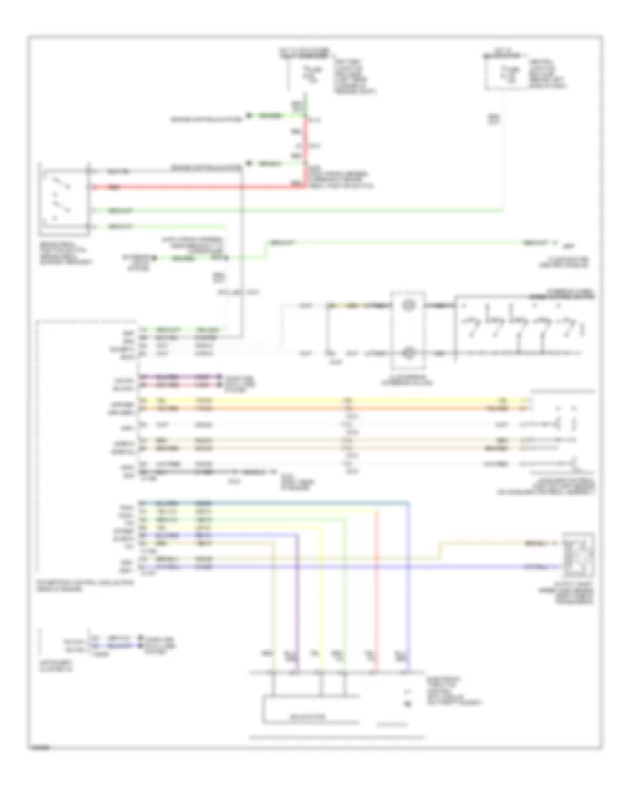
CRUISE CONTROL
Cruise Control Wiring Diagram for Ford Transit Connect 2012
List of elements for Cruise Control Wiring Diagram for Ford Transit Connect 2012:
- (main wiring harness, near breakout to microphone) s234
- 15s-lg23
- 31-re8
- 4-ec7
- 5-ec7
- 7-rj30
- 7-rj35
- 8-pg13
- 8-rj29
- 8-rj30
- 8-rj35
- 9-pg13
- 9-rj29
- 9-rj30
- 9-rj35
- 91s-pg6
- Accelerator pedal position (app) sensor (on accelerator pedal assembly)
- App1
- App2
- Apprtn
- Apprtn2
- Appvref
- Appvref2
- Battery junction box (bjb) (left rear corner of engine compt)
- Bpp
- Bps
- Brake pedal position switch (brake pedal support bracket)
- C175b
- C175e
- C175t
- C213
- C215
- C220b
- Ce412
- Ce426
- Central junction box (cjb) (behind left side of dash)
- Clockspring (steering column)
- Computer data lines system
- Electronic throttle control (etc) module (on throttle body)
- Engine controls system
- Etcref
- Etcrtn
- Exterior lights system
- Floor shifter (center console)
- Fuse 10a
- Fuse 15a
- G100 (right rear of engine)
- Gnd
- Hot in run or start
- Hot w/ pcm power relay energized
- Hs can +
- Hs can -
- Hs can+
- Hs can-
- Instrument cluster (ic)
- Le134
- Nca
- Off
- Oss +
- Oss -
- Output shaft speed (oss) sensor (right side of transmission)
- Powertrain control module (pcm) (rear of engine)
- Re134
- Red
- Rsm
- S103
- S112
- S236 (main wiring harness, in breakout brake pedal position switch)
- Sccs
- Sccsrtn
- Set+
- Set-
- Solid state
- Steering wheel/ speed control switch
- Tacm+
- Tacm-
- Tp1
- Tp2
- Ve818
- Ve819
 English