CRUISE CONTROL
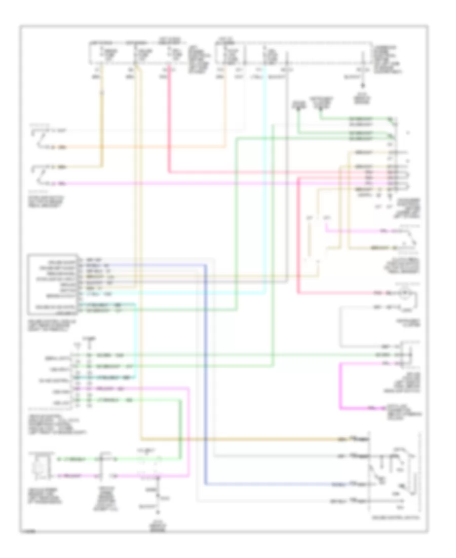
Cruise Control Wiring Diagram for GMC Sierra 2500 1999
List of elements for Cruise Control Wiring Diagram for GMC Sierra 2500 1999:
- (4.3l vin w)
- (other)
- 4.3l
- 4.3l only
- A/t
- A12
- A13
- A14
- A15
- Bare
- Brake cutout
- Brake fuse 10a
- C1 a4
- C1 a6
- C2 f6
- Clutch pedal position switch (on top of clutch pedal bracket)
- Cruise control module (left rear of engine compt, on firewall)
- Cruise control switch
- Cruise fuse 10a
- Cruise on ind cntrl
- Cruise on/off
- Cruise set/coast
- D11
- Data link connector (below steering column)
- F11
- F12
- G115 (rear of engine)
- Ground
- Hot at all times
- Hot in run
- Hot in run and start
- Ign 1 fuse 10a
- Ignition
- Instrument cluster
- Instrument cluster system
- Left bussed electrical center (on lower left side of dash)
- Logic
- M/t
- Mid bussed electrical center (under left left of dash)
- Nca
- Off
- On ind control
- Orn
- Other
- Pnk
- R/a
- Resume/accel
- S103
- Serial data
- Set sw
- Sound system
- Splice pack 205 (left side of dash, behind headlamp switch)
- Stop lps fuse 20a
- Stoplamp sw input
- Stoplamp switch (on top of brake pedal bracket)
- Underhood bussed electrical center (on left side of engine compartment)
- Veh stop fuse 10a
- Vehicle control module (pcm) powertrain control module (vcm) (left front of engine compt)
- Vehicle speed sensor (vss) (left rear side of transmission)
- Vehicle speed sensor adapter (4wd only, except 4.3l)
- Vss high
- Vss input
- Vss low
 English