CRUISE CONTROL
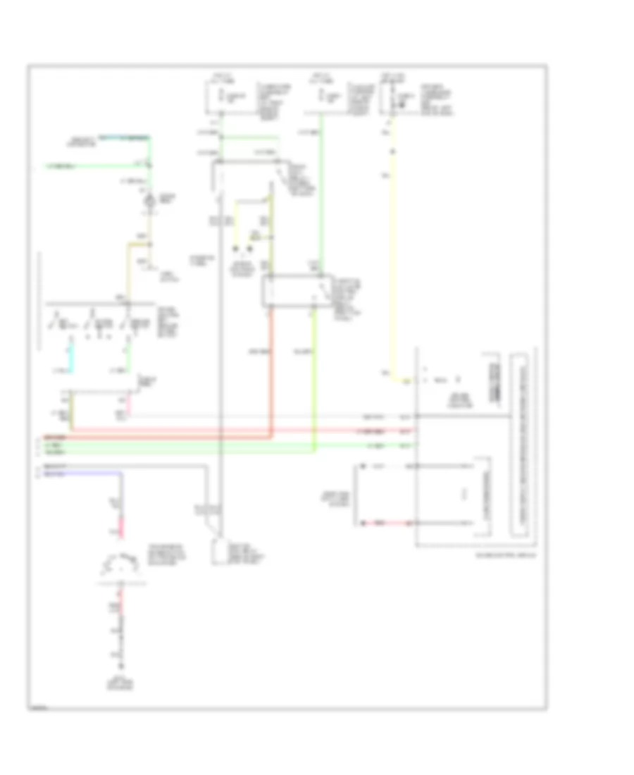
Cruise Control Wiring Diagram, with Navigation (1 of 2) for Honda Pilot LX 2006

List of elements for Cruise Control Wiring Diagram, with Navigation (1 of 2) for Honda Pilot LX 2006:
Cruise Control Wiring Diagram, with Navigation (2 of 2) for Honda Pilot LX 2006
List of elements for Cruise Control Wiring Diagram, with Navigation (2 of 2) for Honda Pilot LX 2006:
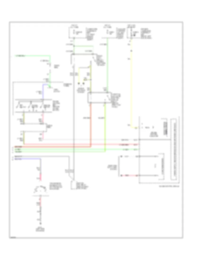
Cruise Control Wiring Diagram, without Navigation (1 of 2) for Honda Pilot LX 2006
List of elements for Cruise Control Wiring Diagram, without Navigation (1 of 2) for Honda Pilot LX 2006:
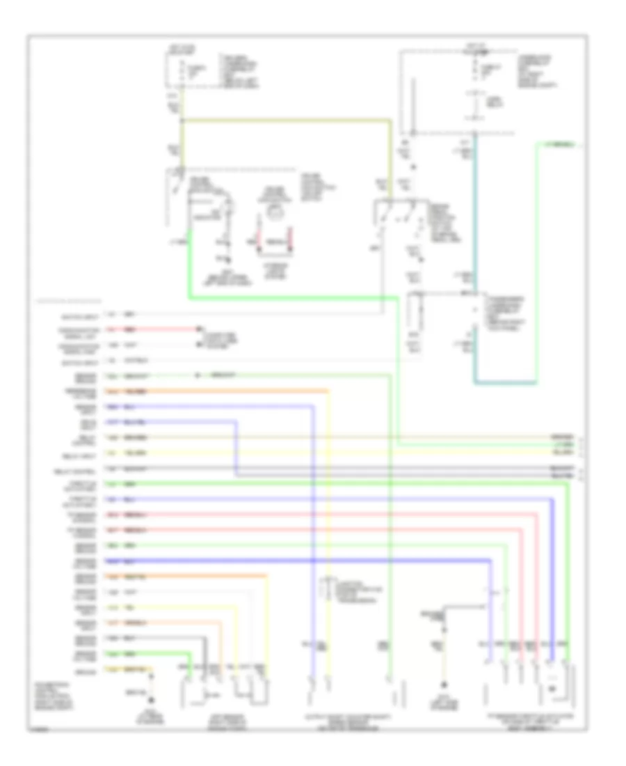
Cruise Control Wiring Diagram, without Navigation (2 of 2) for Honda Pilot LX 2006
List of elements for Cruise Control Wiring Diagram, without Navigation (2 of 2) for Honda Pilot LX 2006: