CRUISE CONTROL
Cruise Control Wiring Diagram for Hummer H3 2008
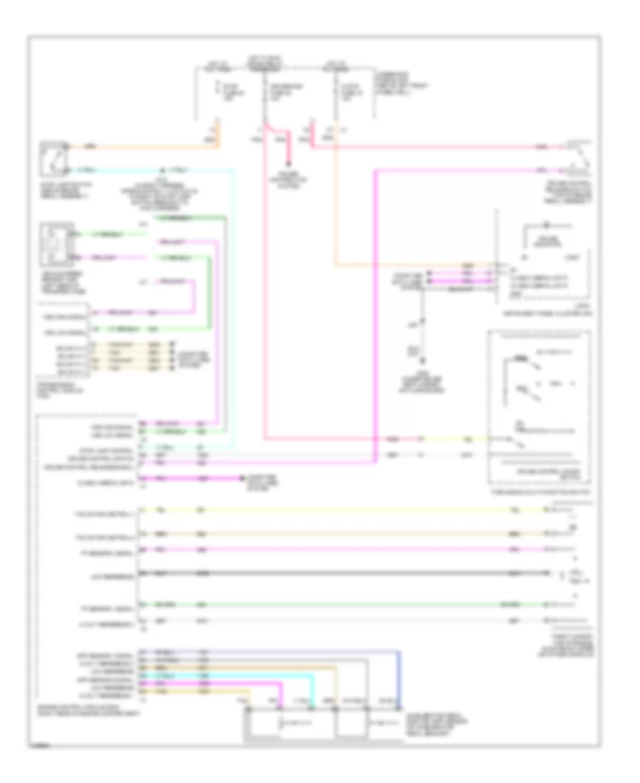
List of elements for Cruise Control Wiring Diagram for Hummer H3 2008:
- 5 volt reference 2
- 5-volt reference 1
- 5-volt reference 2
- A/t
- Accelerator pedal position (app) sensor (on accelerator pedal bracket)
- App sensor 1 signal
- App sensor 2 signal
- Class 2 serial data
- Clstr fuse 19 10a
- Computer data lines system
- Cruise control on/off switch
- Cruise control release signal
- Cruise control release switch (top of brake pedal assembly)
- Cruise control switch
- Cruise indicator
- Cruise/misc fuse 35 10a
- Engine control module (ecm) (right rear of engine compartment)
- G300 (under driver seat carpet, on floor board)
- Gmlan hi (+)
- Gmlan hi (-)
- Gnd
- Hot at all times
- Hot w/ run/ crank relay energized
- Instrument panel cluster (ipc)
- J215 (in body harness, approximately 14 cm (5.5 in) to right of stop lamp switch breakout in main harness)
- J251
- Logic
- Low reference
- M/t
- Off
- On/
- Pnk
- Power distribution system
- Res+
- Set-
- Stop fuse 54 15a
- Stop lamp control
- Stop lamp switch (above brake pedal assembly)
- Tac motor control-1
- Tac motor control-2
- Tan
- Throttle body (top of engine, mounted on upper air intake manifold)
- Tp sensor 1 signal
- Tp sensor 2 signal
- Transmission control module (tcm)
- Turn signal/multi-function switch
- Underhood fuse block (above left front wheelwell)
- Vehicle speed sensor (vss) (left rear of transfer case)
- Vss high signal
- Vss low signal
 English