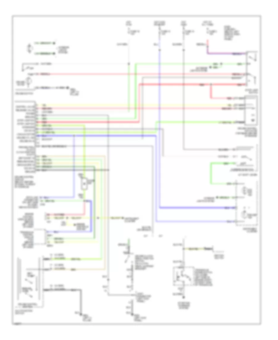
CRUISE CONTROL
Cruise Control Wiring Diagram for Hyundai Tiburon FX 1998
List of elements for Cruise Control Wiring Diagram for Hyundai Tiburon FX 1998:
- (w/ eps)
- (w/o eps)
- A/t
- A/t shift lever
- C01
- Connector (on left side of dash, above coin box)
- Control valve
- Cruise clutch pedal position switch (on clutch pedal support bracket)
- Cruise control actuator (top rear center of engine)
- Cruise control module (below center of dash, in front of console)
- Cruise control switch
- Cruise ctl ind
- Cruise ind
- Cruise on in
- Cruise on ind
- Cruise switch
- Dash fuse box (below left side of dash, at kick panel)
- Data link
- Diagnosis
- Diode z09
- E59-1
- E59-2
- Engine control module (ecm) (behind left side of dash)
- Engine controls system
- Exterior lights system
- Fuse 10 10a
- Fuse 15 10a
- Fuse 16 10a
- Fuse 3 15a
- G200 (left kick panel)
- G904 (left c- pillar)
- Ground
- Hot at all times
- Hot in on
- Hot in on or start
- Ignition switch
- Instrument cluster
- Interior lights system
- Joint connector (left kick panel)
- M-06
- M/t
- Multifunction switch
- N d
- Nca
- O/d off ind
- O/d on in
- Off
- Overdrive switch
- Power
- Prk/neutral in (a/t) cltch postion in (m/t)
- Red
- Release valve
- Resume/ accel
- Resume/accel
- Set/ coast
- Set/coast in
- Starting/ charging system
- Stop lamp sw
- Stop lamp switch
- Transaxle control module (tcm) (behind left side of dash)
- Transaxle range switch (on lower left side of engine compt, on right side of transaxle)
- Vacuum motor
- Vehicle spd in
 English