CRUISE CONTROL
Cruise Control Wiring Diagram (1 of 2) for Hyundai XG350 L 2005

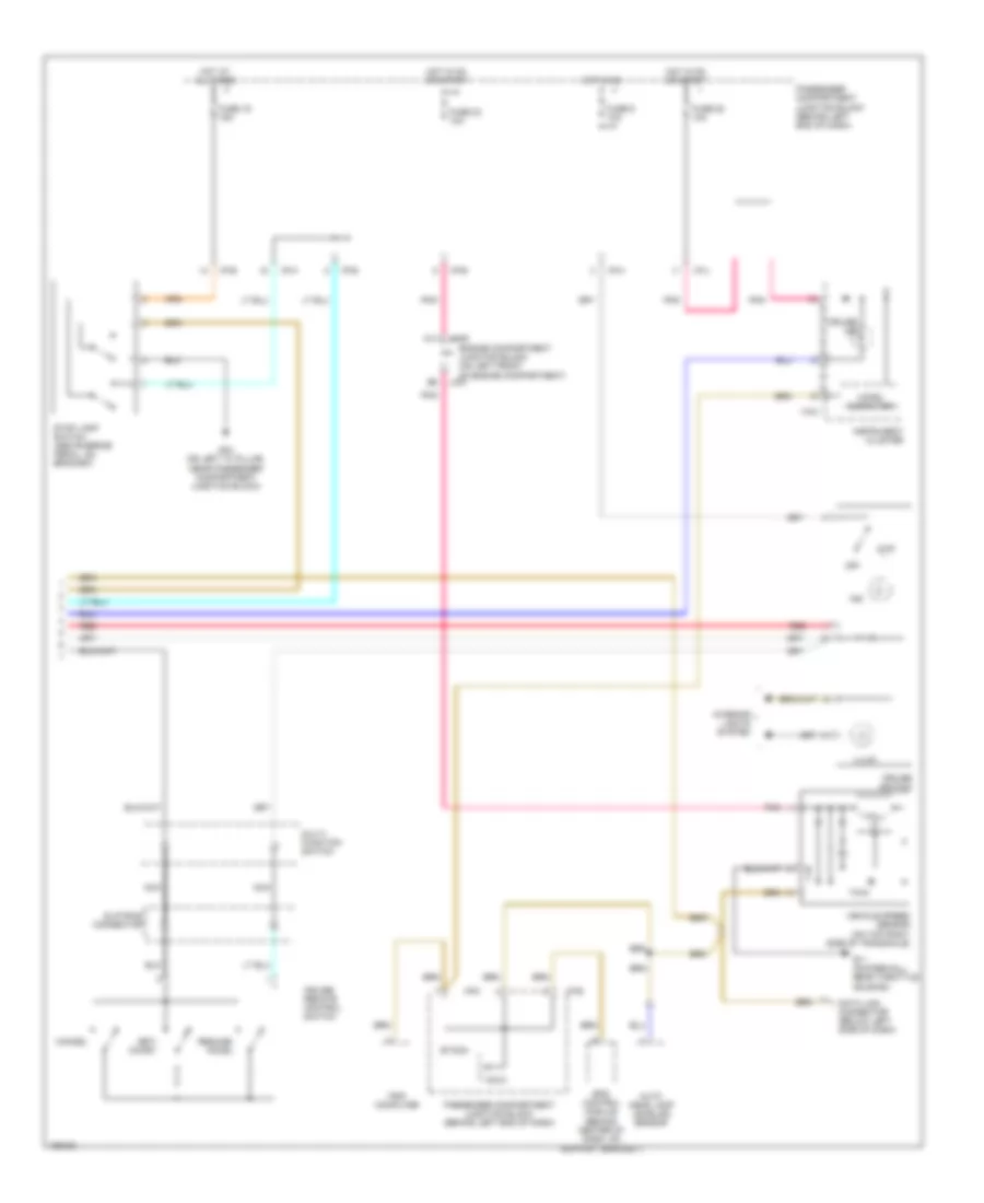
List of elements for Cruise Control Wiring Diagram (1 of 2) for Hyundai XG350 L 2005:
- 87a
- Abs fuse 10a
- Accelerator position sensor (on throttle body)
- Aps sig (main)
- Aps sig (sub)
- Brake sig
- Burglar alarm relay
- C11
- C44-1
- C44-2
- C44-3
- Coast switch gnd
- Coast switch in
- Communication
- Ecm rly on
- Ecu fuse 10a
- Engine compartment junction block (on left front of engine compt)
- Etacm
- Ets control module (behind center of dash, on support bracket)
- Ets ind
- Ets motor (on right side of throttle body)
- Ets relay
- Ets rly cntl
- F10
- Fuse 32 10a
- Fuse 4 15a
- G11 (on firewall, near throttle housing)
- G13 (under center console, right of srs control module)
- G15 (under center console, at left rear of srs control module)
- Ground
- Hot at all times
- Hot in on or start
- Hot in start
- Hot with ecm ctrl relay energized
- I/p-h
- I/p-p
- Idle sw
- Idle switch
- Injector fuse 10a
- J/c c42 (lower left center of dash)
- Jc01
- Jm09
- Limp home valve (on right rear of engine, near throttle body)
- Limp home vlv
- M33-3
- Memory pwr
- Motor
- Motor pwr
- On/start
- Oxygen sensor fuse 15a
- P/n input
- Passenger compartment junction block (behind left end of dash)
- Passenger compartment relay box (behind left end of dash, on support bracket)
- Pcm (behind lower center of dash)
- Pnk
- Red
- Sensor pwr (5v)
- Source
- Start relay
- Start sig
- Stop lamp sw in
- Sw ind
- Throttle position sensor (on left side of throttle body)
- Tps sig (1)
- Tps sig (2)
- Transaxle range switch
- Vehicle speed in
Cruise Control Wiring Diagram (2 of 2) for Hyundai XG350 L 2005
List of elements for Cruise Control Wiring Diagram (2 of 2) for Hyundai XG350 L 2005:
- A11
- Auto head lamp leveling sensor
- Cancel
- Cruise ind
- Cruise remote control switch
- Cruise switch
- Data link connector (below left side of dash)
- Engine compartment junction block (on left front of engine compartment)
- Eps control module (behind center of dash, on support bracket)
- Etacm
- Fuse 19 15a
- Fuse 23 10a
- Fuse 28 10a
- Fuse 9 10a
- G03 (on left "a" pillar, near passenger compartment junction block)
- G11 (on firewall, near throttle housing)
- Hall ic
- Hot at all times
- Hot in on
- Hot in on or start
- I/p-b
- I/p-e
- I/p-h
- I/p-j
- I/p-k
- I18-2
- Illum
- Ind
- Instrument cluster
- Interior lights system
- Jc01
- Jm09
- M33-3
- Micro computer
- Multi- function switch
- Nca
- Off
- Passenger compartment junction block (behind left end of dash)
- Pnk
- Red
- Resume/ accel
- Set/ coast
- Slip ring connector
- Stop lamp switch (above brake pedal, on bracket)
- Trip computer
- Vehicle speed sensor (on top right side of transaxle)