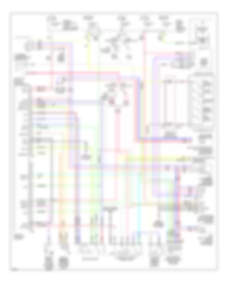
AUTOMOTIVE ELECTRICIANS PORTAL

CRUISE CONTROL – Infiniti FX45 2004 – SYSTEM WIRING DIAGRAMS

CRUISE CONTROL

Cruise Control Wiring Diagram for Infiniti FX45 2004

Cruise Control Wiring Diagram for Infiniti FX45 2004 https://portal-diagnostov.com/license.html
https://portal-diagnostov.com/license.html Automotive Electricians Portal FZCO Automotive Electricians Portal FZCO
Download PDF file

List of elements for Cruise Control Wiring Diagram for Infiniti FX45 2004:

  • (left side of dash)
  • Ascd brake switch (on brake pedal bracket)
  • Ascd steering switch
  • Ascd sw
  • Avcc2
  • Brake sw (close)
  • Brake sw (open)
  • Can-h
  • Can-l
  • Cancel switch
  • Combination meter
  • Combination switch (spiral cable)
  • Computer data lines system
  • Cruise ind (green)
  • E201
  • Early production
  • Electric throttle control actuator (top left rear of engine)
  • Engine control module (ecm) (right end of dash)
  • F101
  • Fuse 12 10a
  • Fuse 14 10a
  • Fuse 19 10a
  • Fuse 20 10a
  • Fuse 87 15a
  • Fuse block (j/b) (behind left kick panel)
  • Gnd-a
  • Gnd-a2
  • Hot at all times
  • Hot in on or start
  • Ipdm e/r (intelligent power distribution module engine room) (right rear of engine compt)
  • J/c 2
  • J/c 3 (upper right end of dash)
  • Late production
  • M15
  • M203
  • M35
  • M45 (behind instrument cluster)
  • M55
  • M90
  • Main switch
  • Motor 1
  • Motor 2
  • Motrly
  • Nca
  • Pnk
  • Red
  • Resume/ accel switch
  • Sensor 1
  • Sensor 2
  • Set ind
  • Set/ coast switch
  • Stop lamp switch (on brake pedal bracket)
  • Throttle control motor relay
  • Tps1
  • Tps2
  • Unified meter & a/c amplifier (behind center console)
  • Unified meter control unit
  • Vmot

Intelligent Cruise Control Wiring Diagram for Infiniti FX45 2004

Intelligent Cruise Control Wiring Diagram for Infiniti FX45 2004 https://portal-diagnostov.com/license.html
https://portal-diagnostov.com/license.html Automotive Electricians Portal FZCO Automotive Electricians Portal FZCO
Get access to all wiring diagrams of the carDownload PDF file

List of elements for Intelligent Cruise Control Wiring Diagram for Infiniti FX45 2004:

  • (left side of dash)
  • (left side of dash) pnk
  • (right side of engine compt) e21
  • A/t assembly (lower rear center of engine compt)
  • Abs actuator & electric unit (control unit) (left rear of engine compt)
  • Accel/ resume switch
  • Ascdsw
  • Bat-1
  • Bat-2
  • Batt
  • Bcm (body control module) (behind left kick panel)
  • Bnc-sw
  • Bncsw
  • Bno-sw
  • Brake booster
  • Brake pressure sensor (left rear of engine compt)
  • Can-h
  • Can-l
  • Cancel switch
  • Combination meter
  • Combination switch (spiral cable)
  • Computer data lines system
  • Cruise ind (green)
  • Data link connector (lower left side of dash)
  • Ddl-rx
  • Ddl-tx
  • Distance switch
  • E201
  • E21 (right side of engine compt)
  • Early production
  • Ecm (engine control module) (right end of dash)
  • Fuse & fusible link block (right rear of engine compt)
  • Fuse 12 10a
  • Fuse 14 10a
  • Fuse 19 10a
  • Fuse 20 10a
  • Fuse 35 10a
  • Fuse block (j/b) (behind left kick panel)
  • Gnd
  • Gnd-1
  • Gnd-2
  • Gnd-3
  • Gnd-a
  • Hot at all times
  • Hot in on or start
  • Icc brake hold relay (in relay box)
  • Icc brake switch (on brake pedal bracket)
  • Icc sensor (lower front of engine compt)
  • Icc steering switch
  • Icc unit (right end of dash)
  • Ign
  • Ign-1
  • Ign-2
  • J/c 2
  • Late production
  • M15
  • M203
  • M35 (left side of dash)
  • M45 (behind instrument cluster)
  • M55
  • M56
  • M88
  • M89
  • M90
  • Main switch (on/off)
  • Neut-sw
  • Parking brake switch (at base of parking brake lever)
  • Pkb-sw
  • Pnk
  • Psen-gnd
  • Psen-pwr
  • Psen-sig
  • Pwr gnd
  • Red
  • Rls-nc
  • Rls-no
  • Rls-pwr
  • Set ind
  • Set/ coast switch
  • Sol+
  • Sol-
  • Start-rly
  • Stop light switch (on brake pedal bracket)
  • Stp-lmp
  • Tcm
  • Unified meter & a/c amplifier (behind center console)
  • Unified meter control unit
  • V out
  • V pwr
  • Vdc/tcs/abs control unit