CRUISE CONTROL
Cruise Control Wiring Diagram (1 of 2) for Infiniti G25 Journey 2012

List of elements for Cruise Control Wiring Diagram (1 of 2) for Infiniti G25 Journey 2012:
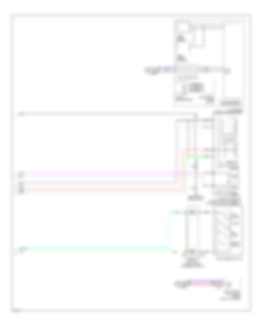
Cruise Control Wiring Diagram (2 of 2) for Infiniti G25 Journey 2012
List of elements for Cruise Control Wiring Diagram (2 of 2) for Infiniti G25 Journey 2012: