CRUISE CONTROL
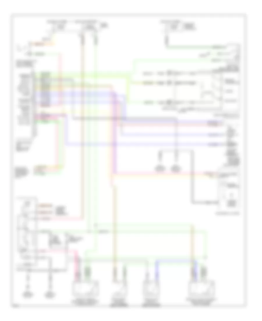
Cruise Control Wiring Diagram, A/T for Infiniti I30 t 1996

List of elements for Cruise Control Wiring Diagram, A/T for Infiniti I30 t 1996:
- A/t control unit (left kick panel)
- Act. cntrl
- Actuator control
- Air valve solenoid
- Ascd cancel switch (top of brake pedal support)
- Ascd control unit (below left side of i/p)
- Ascd hold relay (relay box 1, left front of engine compt)
- Ascd pump (left rear of engine compartment)
- Ascd steering switch
- Ascd sw.
- Ascd switch
- Cancel
- Crs. cancl
- Cruise
- Cruise indicator
- Cruise signal
- Data line
- Data link connector for consult (left side of i/p)
- Fuse 10 15 amp
- Fuse 12 7.5 amp
- Fuse 17 10 amp
- Fuse 64 15 amp
- Fuse and fusible link block
- Fuse block
- G100 (left front fender)
- G101 (right front fender)
- G120 (right side of engine)
- G202 (left side of i/p)
- G203 (left kick panel)
- Ground
- Horn relay (relay box 1, left front of engine compt)
- Horn switch
- Horns
- Hot at all times
- Hot in on or start
- Illum.
- Inhibitor relay (relay box 1, left front of engine compartment)
- Inhibitor switch (left side of transmission)
- Instrument cluster
- Interior lights system
- Interior lights system (rheostat)
- Nca
- Od cut signal
- Off
- On ind.
- Pnk
- Release valve solenoid
- Resume/ accelerate
- Set/coast
- Speed
- Spiral cable
- Steering switch
- Stop lamp switch (top of brake pedal support)
- Stop lamp switch od cut
- Theft warning relay 2 (relay box-2, right front fender)
- Vacuum motor
- Vehicle speed output
Cruise Control Wiring Diagram, M/T for Infiniti I30 t 1996
List of elements for Cruise Control Wiring Diagram, M/T for Infiniti I30 t 1996:
- Act. cntrl
- Actuator control
- Air valve solenoid
- Ascd cancel switch (top of brake pedal support)
- Ascd clutch switch (top of clutch pedal support)
- Ascd clutch switch relay (relay box 2, right front fender)
- Ascd control unit (below left side of i/p)
- Ascd hold relay (relay box 1, left front of engine compt)
- Ascd pump (left rear of engine compartment)
- Ascd steering switch
- Ascd sw.
- Ascd switch
- Cancel
- Crs. cancl
- Cruise
- Cruise indicator
- Data line
- Data link connector for consult (left side of i/p)
- Fuse 10 15 amp
- Fuse 12 7.5 amp
- Fuse 64 15 amp
- Fuse and fusible link block
- Fuse block
- G100 (left front fender)
- G101 (right front fender)
- G202 (left side of i/p)
- G203 (left kick panel)
- Ground
- Horn relay (relay box 1, left front of engine compt)
- Horn switch
- Horns
- Hot at all times
- Hot in on or start
- Illum.
- Instrument cluster
- Interior lights system
- Interior lights system (rheostat)
- Nca
- Off
- On ind.
- Pnk
- Release valve solenoid
- Resume/ accelerate
- Set/coast
- Speed
- Spiral cable
- Steering switch
- Stop lamp switch (top of brake pedal support)
- Stop lamp switch od cut
- Vacuum motor
- Vehicle speed output