CRUISE CONTROL
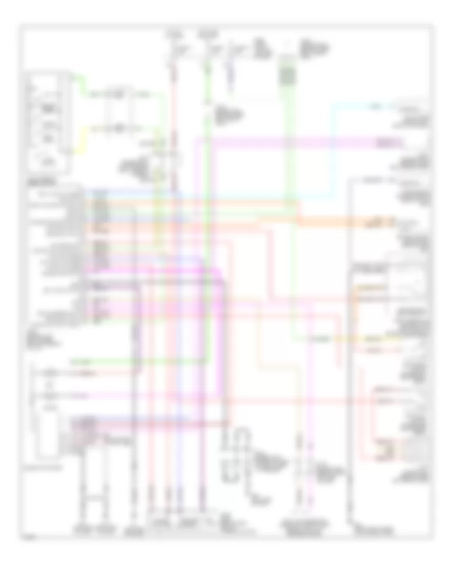
Cruise Control Wiring Diagram for Infiniti Q45 2002
List of elements for Cruise Control Wiring Diagram for Infiniti Q45 2002:
- 21r
- 24r
- 29r
- 31r
- Actr high side
- Air valve
- Air valve low side
- Ascd brake switch (on bracket, above brake pedal)
- Ascd control unit (behind dash, left of steering column)
- Ascd pump (behind dash, left of steering column)
- Ascd steering wheel switch
- Brake sw input
- Cancel
- Combination meter
- Computer data lines
- Control sw (a/d) input
- Control sw input (gnd)
- Cruise
- Cruise lamp input
- Data link connector (under left side of dash, beside hood lock release handle)
- E24 (near fuse, fusible link and relay box)
- Ecm prun input
- Engine control module (ecm) (behind glove box)
- Etc prun
- F8 (left side of engine)
- Fuse 12 10a
- Fuse 17 15a
- Fuse 9 10a
- Fuse block (j/b) no.1 (left end of dash)
- Fuse, fusible link and relay box (right front of engine compartment)
- Gnd
- Gnd-c
- Hot at all times
- Hot in on and start
- Ign sw
- Joint connector 12 (top center of dash, taped to harness)
- Joint connector 16 (behind upper right side of dash)
- Joint connector 18 (behind upper right side of dash)
- Joint connector 4 (behind upper left side of dash)
- Joint connector 5 (upper left side of dash, taped to harness)
- Joint connector 7 (behind upper left side of dash)
- Joint connector 8 (behind upper left side of dash)
- M114 (right side of dash)
- M24 (left side of dash)
- M25 (left side of dash)
- Main switch
- Motor low side
- Od cancel sw
- Park/neutral position relay
- Rel valve low side
- Release valve
- Resume/ accel
- Rxi
- Set
- Set lamp output
- Set/ coast
- Solenoid monitor input
- Start rly
- Stoplight switch (on bracket above brake pedal)
- Tcs input
- Throttle position input
- Transmission control module (behind glove box)
- Tvo0
- Txi
- Vacuum motor
- Vdc/tcs/abs control unit (right kick panel)
- Vehicle speed input
 English