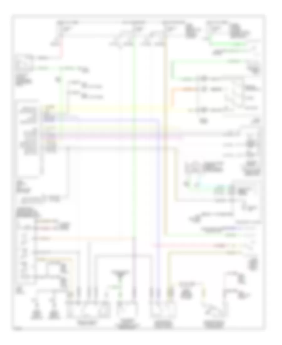
CRUISE CONTROL
Cruise Control Wiring Diagram for Infiniti QX4 1998
List of elements for Cruise Control Wiring Diagram for Infiniti QX4 1998:
- (behind left headlamp)
- (behind right headlamp)
- 14u
- 23u
- 39u
- Act power
- Air valve
- Ascd 4th cut sw
- Ascd actuator (right front fender well)
- Ascd brake switch (on bracket, above brake pedal)
- Ascd control unit (behind left kick panel)
- Ascd cruise sw
- Ascd hold relay (in relay box 1)
- Ascd main switch
- Ascd switch
- Brake n/c sw
- Brake n/o sw
- Cancel
- Cruise ind
- Diode (behind left side of dash)
- Electronic speed- ometer
- Fuse & fusible link box (on right front fender well, in relay box 2)
- Fuse 11 7.5a
- Fuse 14 10a
- Fuse 18 10a
- Fuse 54 10a
- G106
- G107
- G200 (left kick panel)
- G203 (right kick panel)
- Gnd
- Horn relay (in relay box 1)
- Horns system
- Hot at all times
- Hot in on or start
- Hot in on or start fuse block behind dash, left of steering column)
- Inhibitor switch (on right side of transmission)
- Instrument cluster
- Interior lights system
- Main sw
- Nca
- Od cancel sig
- Off
- Park/neutral position relay (in relay box 2)
- R p
- Rel valve
- Release valve
- Res/acc sw
- Resume/ accelerate
- Set/coast
- Set/coast sw
- Smart entrance control unit
- Spiral cable
- Stop lamps
- Stoplight switch (on bracket, above brake pedal)
- Theft warning relay (in relay box 1)
- Transmission control module (behind dash, left of steering column)
- Transmissions system
- Vac motor
- Vacuum motor
- Vehicle speed sensor (right side of transmission)
- Vss
 English