CRUISE CONTROL
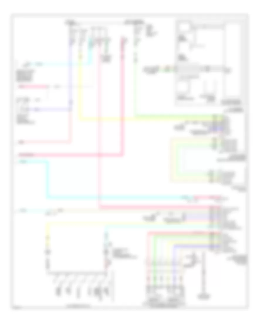
Cruise Control Wiring Diagram (1 of 2) for Infiniti QX50 2014

List of elements for Cruise Control Wiring Diagram (1 of 2) for Infiniti QX50 2014:
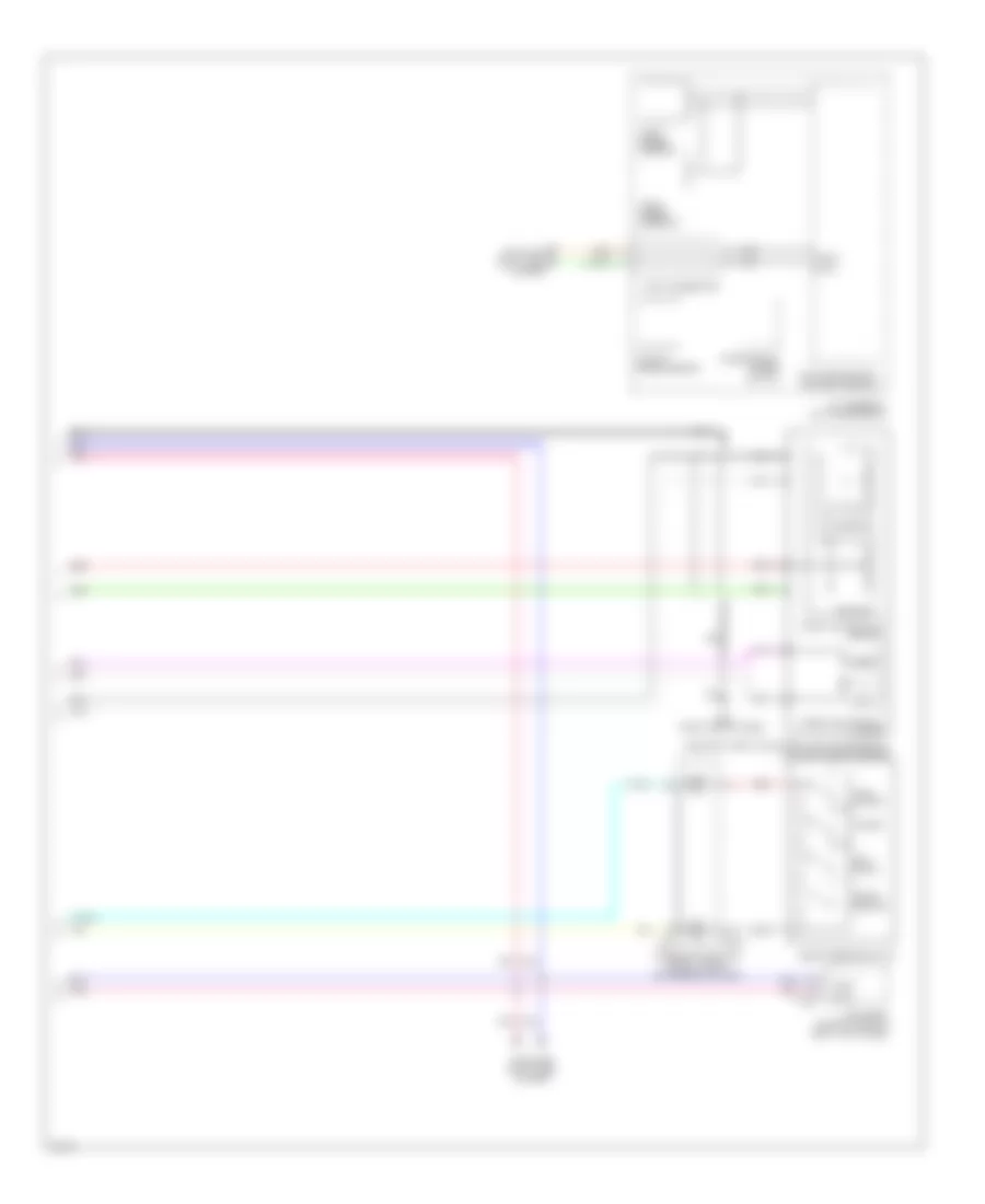
Cruise Control Wiring Diagram (2 of 2) for Infiniti QX50 2014
List of elements for Cruise Control Wiring Diagram (2 of 2) for Infiniti QX50 2014:
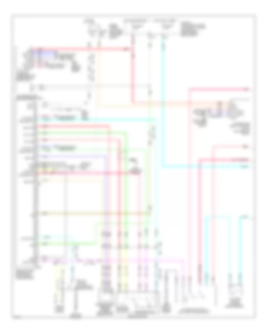
Intelligent Cruise Control Wiring Diagram (1 of 2) for Infiniti QX50 2014
List of elements for Intelligent Cruise Control Wiring Diagram (1 of 2) for Infiniti QX50 2014:
Intelligent Cruise Control Wiring Diagram (2 of 2) for Infiniti QX50 2014
List of elements for Intelligent Cruise Control Wiring Diagram (2 of 2) for Infiniti QX50 2014: