CRUISE CONTROL
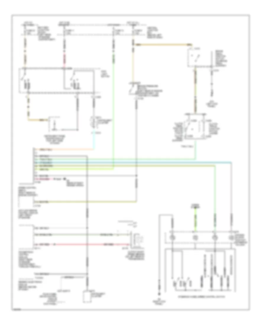
Cruise Control Wiring Diagram for Mazda B4000 2002
List of elements for Cruise Control Wiring Diagram for Mazda B4000 2002:
- 1000 ohms
- 120 ohms
- 15a
- 680 ohms
- 7.5a
- A-206
- A/t
- Air bag sliding contact (steering column)
- Antilock brake control module (left front of engine)
- B-111
- B-176
- Battery junction block (left rear of engine compartment)
- Brake pedal position switch (on brake pedal support)
- Brake pressure switch (left rear of engine compartment, on master cylinder)
- C-214
- C-215
- Central junction box (behind left side of dash)
- Clutch pedal position switch (top of clutch pedal support)
- Clutch triple function switch jumper
- Coast
- Four wheel drive control module (in right kick panel)
- Fuse 10
- Fuse 11
- Fuse 33
- Fuse 9
- G10 (left kick panel)
- G5 (rear of right fender apron)
- G8 (right kick panel)
- Generic electronic module (behind center of dash)
- H-281a
- Head
- Horn
- Horns system
- Hot at all times
- Hot in on or start
- Hot in run
- Instrument cluster
- Instrument panel dimming module (top left side of dash)
- M/t
- Main light switch
- N-138
- N-165
- N-219
- Nca
- O-154
- Off
- Output shaft speed sensor (on left rear of transmission)
- Park
- Powertrain control module (right rear of engine compartment, through firewall)
- Rest
- Resume
- Set/accelerate
- Speed contrl off 2200 ohms
- Speed contrl on
- Speed control servo (right rear of engine compart)
- Steering wheel/speed control switch
- T-2100a
- X-205
- X-210
 English