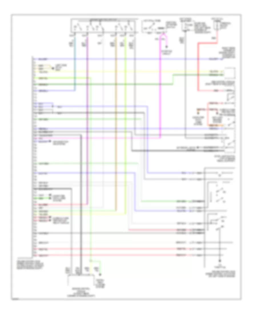
CRUISE CONTROL
Cruise Control Wiring Diagram for Mercedes-Benz 300E 1993

List of elements for Cruise Control Wiring Diagram for Mercedes-Benz 300E 1993:
- (behind left side of instrument cluster)
- Acc/ set
- C 1995 vftc
- Cntrl in
- Cntrl out
- Control trans- mission
- Cruise control actuator (lower left side of engine)
- Cruise control amplifier (behind lower left side of dash)
- Cruise control switch
- Dec/ set
- Disengage
- Feedback
- Feedback in
- Fuse 5 8a
- Fuse/ relay box (left side of component compartment)
- G202
- G202 (behind left side of instrument cluster)
- Ground
- Hall-effect speed sensor (rear of instrument cluster)
- Hot in run or start
- Mtr cntrl out
- Multipoint connector (behind right side of instrument cluster)
- Off
- Red
- Reference resistor
- Release clutch
- Resume
- Stop lamp switch (closed w/ brake pedal depressed)
- Veh speed in
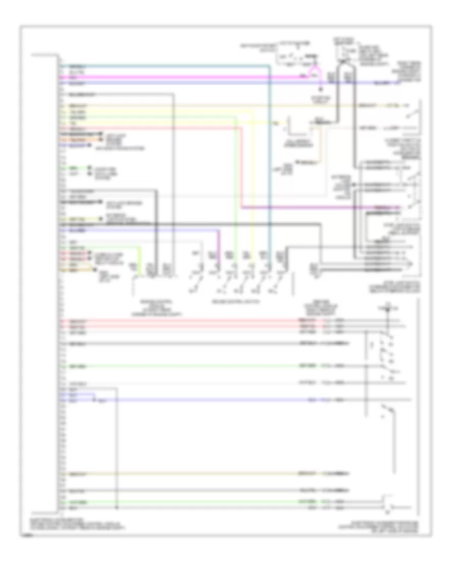
Cruise/Idle Speed Control Wiring Diagram for Mercedes-Benz 300E 1993
List of elements for Cruise/Idle Speed Control Wiring Diagram for Mercedes-Benz 300E 1993:
- (left side of i/p) g202
- (right rear corner of engine compt) diagnostic connector
- 15a
- Abs control module (right rear of eng compt)
- Acc
- Air condition- ing system
- Ant-lock brakes system
- Computer data lines system
- Cruise control switch
- Cruise control/idle speed control actuator (on left side of engine)
- Cruise control/idle speed control module (in module box, on right rear of engine compt)
- Engine control module (in right rear corner of engine compt)
- Exterior lights system
- Fuse 8a
- Fuse and relay box (on left rear corner of engine compt)
- Hot at all times
- Hot in run or start
- Ignition/ starter switch
- Instru- ment cluster system
- Nca
- Off
- Overvoltage protection relay module
- Red
- Run
- Start
- Starting circuit
- Stop lamp switch (top of brake pedal support)
- Terminal block x4/10
- To throttle
Electronic Accelerator/Cruise/Idle Speed Control Wiring Diagram for Mercedes-Benz 300E 1993
List of elements for Electronic Accelerator/Cruise/Idle Speed Control Wiring Diagram for Mercedes-Benz 300E 1993:
- (right rear corner of engine compt) diagnostic connector
- Abs/asr control module (right rear of engine compt)
- Acc
- Air conditioning system
- Anti-lock brakes system
- Closed throttle position switch (on top of accelerator bracket)
- Computer data lines system
- Cruise control switch
- Electronic accelerator/ cruise control/idle speed control module (in module box, on right rear of engine compt)
- Electronic accelerator/cruise control/idle speed control actuator (on left side of engine)
- Engine control module (in right rear corner of engine compt)
- Exterior lamp failure monitor- ing module
- Exterior lights system (backup lamp switch)
- Fuse 8a
- Fuse and relay box (on left rear corner of engine compt)
- G202 (left side of i/p)
- Hall-effect speed sensor
- Hot at all times
- Hot in run or start
- Ignition/starter switch
- Nca
- Off
- Overvoltage protection relay module
- Run
- Start
- Starting circuit
- Stop lamp switch (top of brake pedal support)
- Stop lamp switch intermediate connector (below steering column)
- To throttle