CRUISE CONTROL
Cruise Control Wiring Diagram for Mercedes-Benz C220 1994

List of elements for Cruise Control Wiring Diagram for Mercedes-Benz C220 1994:
- 12/3
- Abs control module/ electronic traction system/speed sensitive power steering module (right component compartment)
- Acc/ set
- Cruise control actuator
- Cruise control module (right component compartment)
- Cruise control switch
- Dec/ set
- Engine control module (right rear corner of engine compt)
- Fuse 10a
- Fuse box (left rear corner of engine compt)
- G105 (rear of right front fender)
- Hot in run or start
- Nca
- Off
- Overvoltage protection relay module
- Red
- Reference resistor
- Resume
- Stop lamp switch
- Terminal block x21/1 (right kick panel)
- Terminal block x62/13 (right kick panel)
- To throttle
- Vehicle speed sensor
Cruise/Idle Speed Control Wiring Diagram for Mercedes-Benz C220 1994
List of elements for Cruise/Idle Speed Control Wiring Diagram for Mercedes-Benz C220 1994:
- (right kick panel) j/b x62/12
- (right of rear front fender) g105
- (right rear corner of engine compt) data link connector
- 12/3
- 15a
- 87z
- Abs control module (right component compt)
- Acc
- After 11/93
- Air condition- ing system
- Before 11/93
- Can h
- Can l
- Cruise control switch
- Cruise control/idle speed control actuator
- Cruise control/idle speed control module (right component compartment)
- Dfa ha
- Dfa vl
- Engine control module (in right rear corner of engine compt)
- Engine/chassis connector (left side of engine compt)
- Exterior lights system
- Fuse 10a
- Fuse box (left rear corner of engine compt)
- Hot at all times
- Hot in run or start
- Ignition/ starter switch
- J/b x4/22 (right kick panel)
- J/b x62/13 (right kick panel)
- Nca
- Off
- Over- voltage pro- tection relay module
- Overvoltage protection relay module (right rear corner of engine compt)
- Red
- Run
- Start
- Starter/ lock- out relay module (right kick panel)
- Stop lamp switch
- To throttle
- Vehicle speed sensor
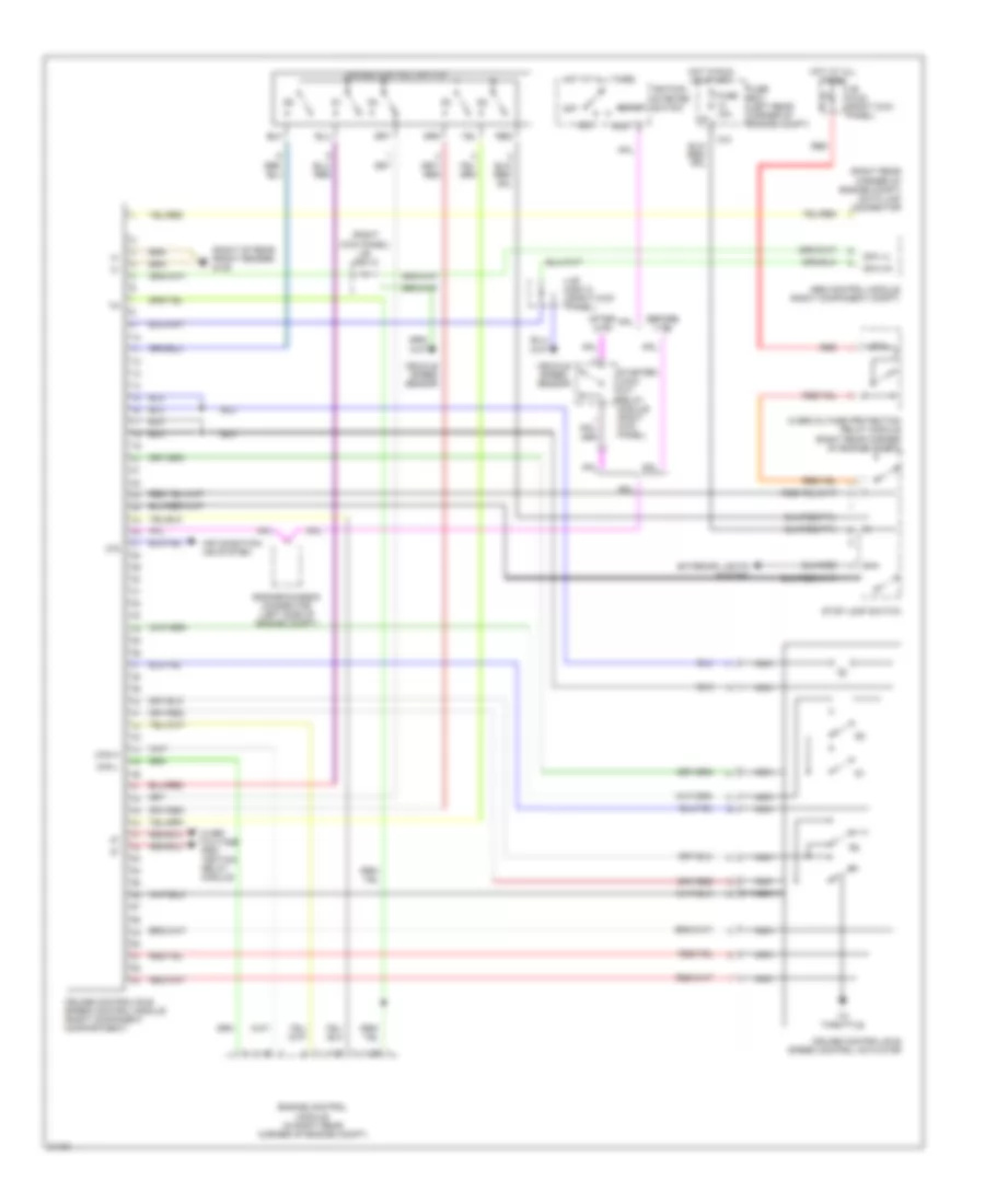
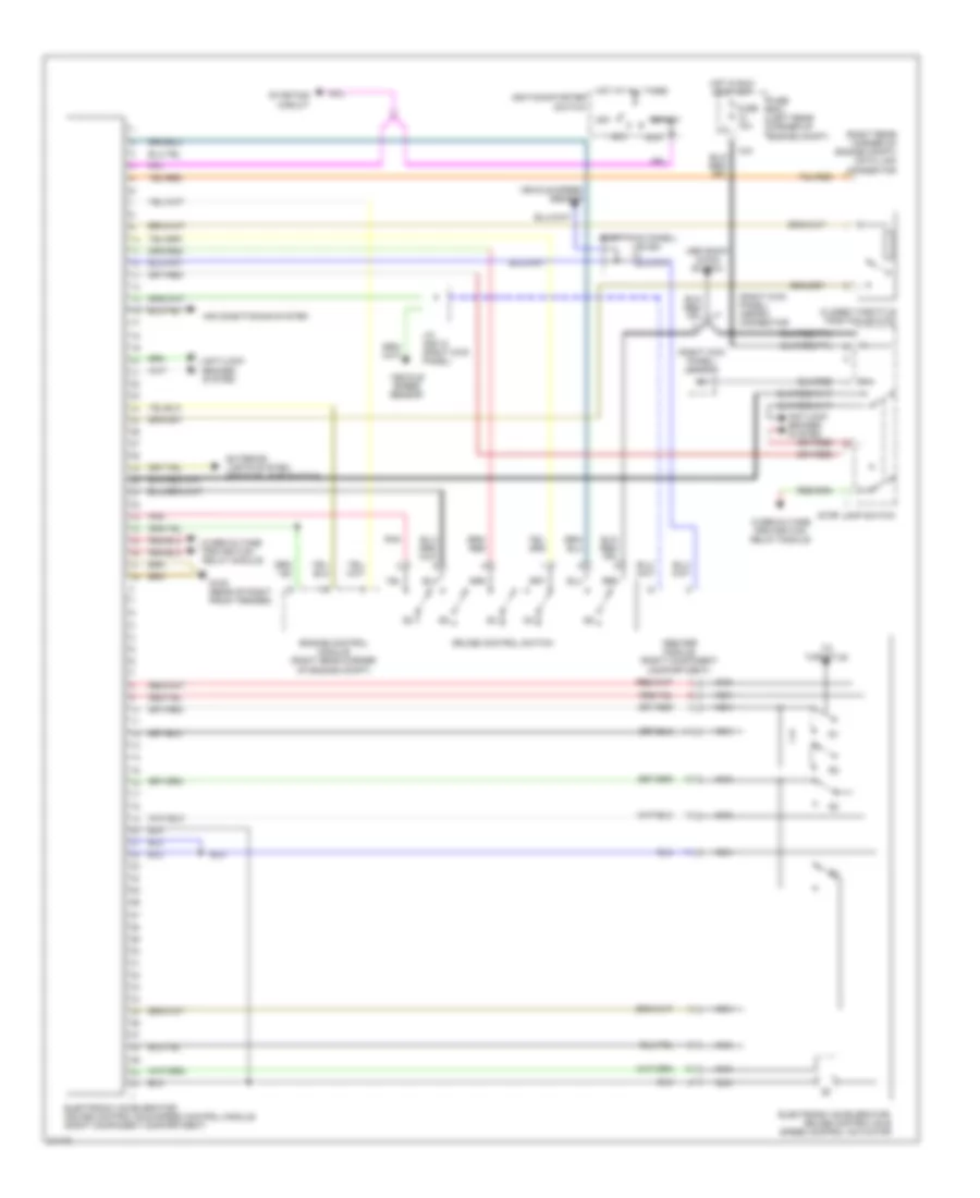
Electronic Accelerator/Cruise/Idle Speed Control Wiring Diagram for Mercedes-Benz C220 1994
List of elements for Electronic Accelerator/Cruise/Idle Speed Control Wiring Diagram for Mercedes-Benz C220 1994:
- (right kick panel)
- (right kick panel) asr/ea connector
- (right kick panel) j/b x21/1
- (right rear corner of engine compt) data link connector
- 12/3
- Abs/asr module (right component compartment)
- Acc
- Air conditioning system
- Ant-lock brakes system
- Anti-lock brakes system
- Asr snow chain switch
- Closed throttle position switch
- Cruise control switch
- Electronic accelerator/ cruise control/idle speed control actuator
- Electronic accelerator/ cruise control/idle speed control module (right component compartment)
- Engine control module (right rear corner of engine compt)
- Exterior lights system (backup lamp switch)
- Fuse 10a
- Fuse box (left rear corner of engine compt)
- G105 (rear of right front fender)
- Hot at all times
- Hot in run or start
- Ignition/starter switch
- J/c x62/12 (right kick panel)
- Nca
- Off
- Overvoltage protection relay module
- Pnk
- Red
- Run
- Start
- Starting circuit
- Stop lamp switch
- To throttle
- Vehicle speed sensor