CRUISE CONTROL
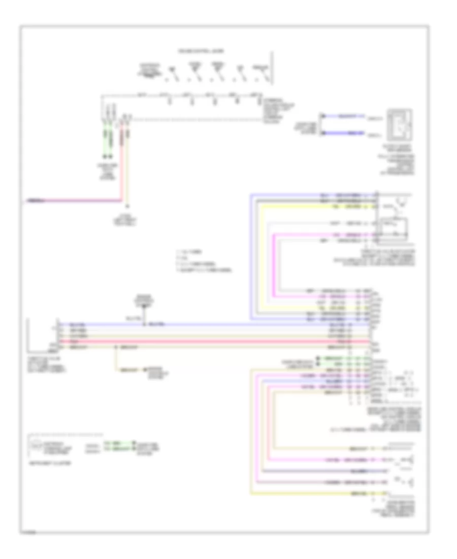
Cruise Control Wiring Diagram (1 of 2) for Mercedes-Benz C350 2014

List of elements for Cruise Control Wiring Diagram (1 of 2) for Mercedes-Benz C350 2014:
- (left front of engine compt)
- (pins 20-31 are not used)
- (top of brake pedal assembly) stop lamp switch
- 12i
- 14i
- 30g
- Bls 12v
- Bls h
- Bls_l
- Bls_m
- C2i
- C5c
- Can e h
- Can e l
- Can g h
- Can g l
- Can h h
- Can h l
- Can s h
- Can s l
- Computer
- Computer data lines system
- Data lines
- Distronic control unit
- Distronic electric controller unit (center of front grille)
- Distronic radar sensor
- Electronic stability
- Front sam control module w/ fuse & relay module (left rear of engine compt)
- Fuse 5a
- Fuse 7.5a
- Hot at all times
- Hot w/ chassis circuit 87 relay energized
- Hot w/ circuit 15 relay energized
- Hot w/ quiescent current cutout relay energized
- Left front bumper distronic sensor (dtr)
- Left rear bumper intelligent radar sensor (w/ blind spot assist)
- Left rear bumper radar sensor (behind left end of rear bumper)
- Lvds n
- Lvds p
- Multi-function camera
- Pnk
- Program control unit
- Rear sam control module w/ fuse & relay module (right side of trunk/ cargo area)
- Right front bumper distronic sensor (dtr)
- Right rear bumper intelligent radar sensor (w/ blind spot assist)
- Right rear bumper radar sensor (behind right rear end of rear bumper)
- System
- Video & radar sensor system control unit
- Video n
- Video p
- W15/7 (right front footwell)
- W7 (right side of cargo area/ trunk)
- X26/38
- X35/28
Cruise Control Wiring Diagram (2 of 2) for Mercedes-Benz C350 2014
List of elements for Cruise Control Wiring Diagram (2 of 2) for Mercedes-Benz C350 2014:
- (+)
- (+) sv
- +5v
- 1.8l turbo
- 2.1l turbo diesel
- 3.5l
- Acc
- Accel/ set
- Accelerator pedal sensor (top of accelerator pedal assembly)
- Can c h
- Can c l
- Can e h
- Can e l
- Can-e h
- Can-e l
- Computer data lines system
- Cruise control lever
- Dcm
- Dcp
- Dec
- Decel/ set
- Distronic control (if equipped)
- Distronic warning lamp (if equipped)
- Engine controls system
- Except 2.1l turbo diesel
- Fully integrated transmission control control unit (in transmission)
- Gnd
- Ind
- Instrument cluster
- Ip1s
- Ip2s
- Ipm
- Me-sfi (me) control module (except 2.1l turbo diesel) cdi control module (2.1l turbo diesel) (3.5l: left side of engine) (2.1l turbo diesel: top right rear of engine)
- Off
- Output shaft rpm sensor
- Pnk
- Res
- Resume
- Sig
- Sp1m
- Sp1s
- Sp2m
- Sp2s
- Steering column module control unit (top of steering column)
- Throttle valve actuator (2.1l turbo diesel) (on throttle body)
- Throttle valve actuator (except 2.1l turbo diesel) (glk class 3.5l & 1.8l: on throttle body) (c class 3.5l: in air intake manifold)
- U-pwg1
- W15/5 (left front footwell)