CRUISE CONTROL
Cruise Control Wiring Diagram for Mercedes-Benz E320 2003

List of elements for Cruise Control Wiring Diagram for Mercedes-Benz E320 2003:
- 2003 & 2004 early prod
- 2004 late prod & 2005
- Accel/ set
- Accelerator pedal sensor (above accelerator pedal)
- Can-b h
- Can-b l
- Can-c h
- Can-c l
- Computer data lines system
- Cruise control switch
- Decel/ set
- Driver side sam control module with fuse & relay module (left rear of eng compt)
- Engine control module (me-sfi) (left rear of eng compt)
- Fuse 7.5a
- Hot at all times
- Interior fuse box (left end of dash)
- Memory recall
- Off
- Red
- Steering column module (in steering wheel)
- Throttle valve actuator (rear of eng)
- W15/1 (right front footwell)
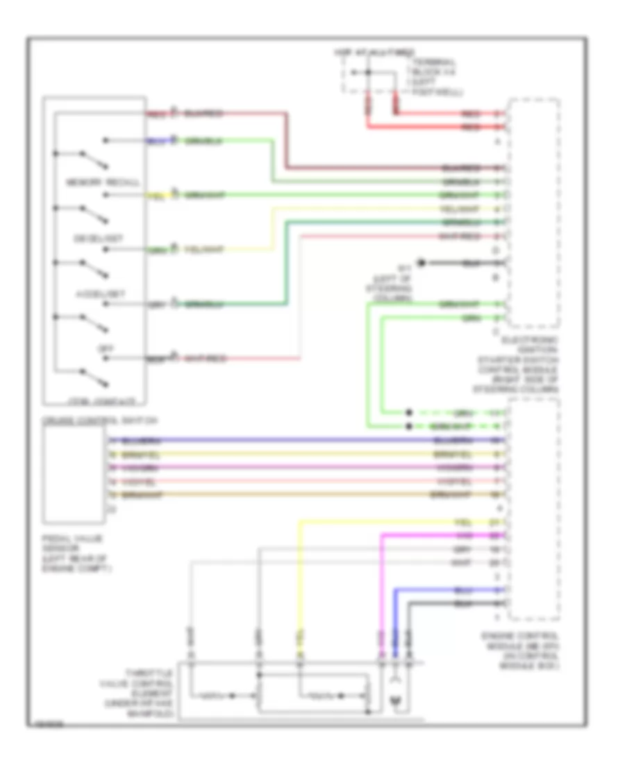
Cruise Control Wiring Diagram, Wagon for Mercedes-Benz E320 2003
List of elements for Cruise Control Wiring Diagram, Wagon for Mercedes-Benz E320 2003:
- Accel/set
- Cruise control switch
- Ctrl contact
- Decel/set
- Electronic ignition- starter switch control module (right side of steering column)
- Engine control module (me-sfi) (in control module box)
- Hot at all times
- Memory recall
- Off
- Pedal value sensor (left rear of engine compt)
- Red
- Terminal block x4 (left footwell)
- Throttle valve control element (under intake manifold)
- W1 (left of steering column)
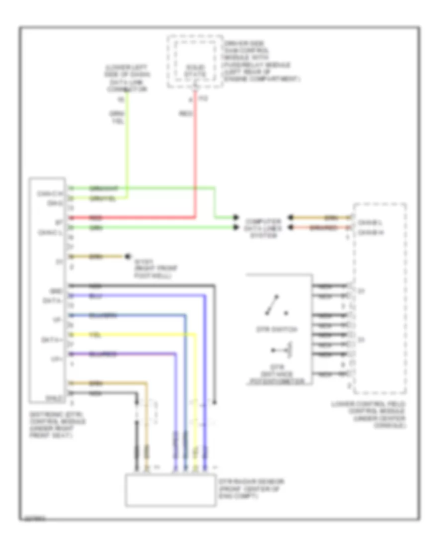
Electronic Accelerator/Cruise/Idle Speed Control Wiring Diagram, Early Production for Mercedes-Benz E320 2003
List of elements for Electronic Accelerator/Cruise/Idle Speed Control Wiring Diagram, Early Production for Mercedes-Benz E320 2003:
- (lower left side of dash) data link connector
- Can-b h
- Can-b l
- Can-c h
- Can-c l
- Computer data lines system
- Data+
- Data-
- Diag
- Distronic (dtr) control module (under right front seat)
- Driver side sam control module with fuse/relay module (left rear of engine compartment)
- Dtr distance potentiometer
- Dtr radar sensor (front center of eng compt)
- Dtr switch
- Gnd
- I12
- Lower control field control module (under center console)
- Nca
- Red
- Shld
- Solid state
- Vf+
- Vf-
- W15/1 (right front footwell)