CRUISE CONTROL
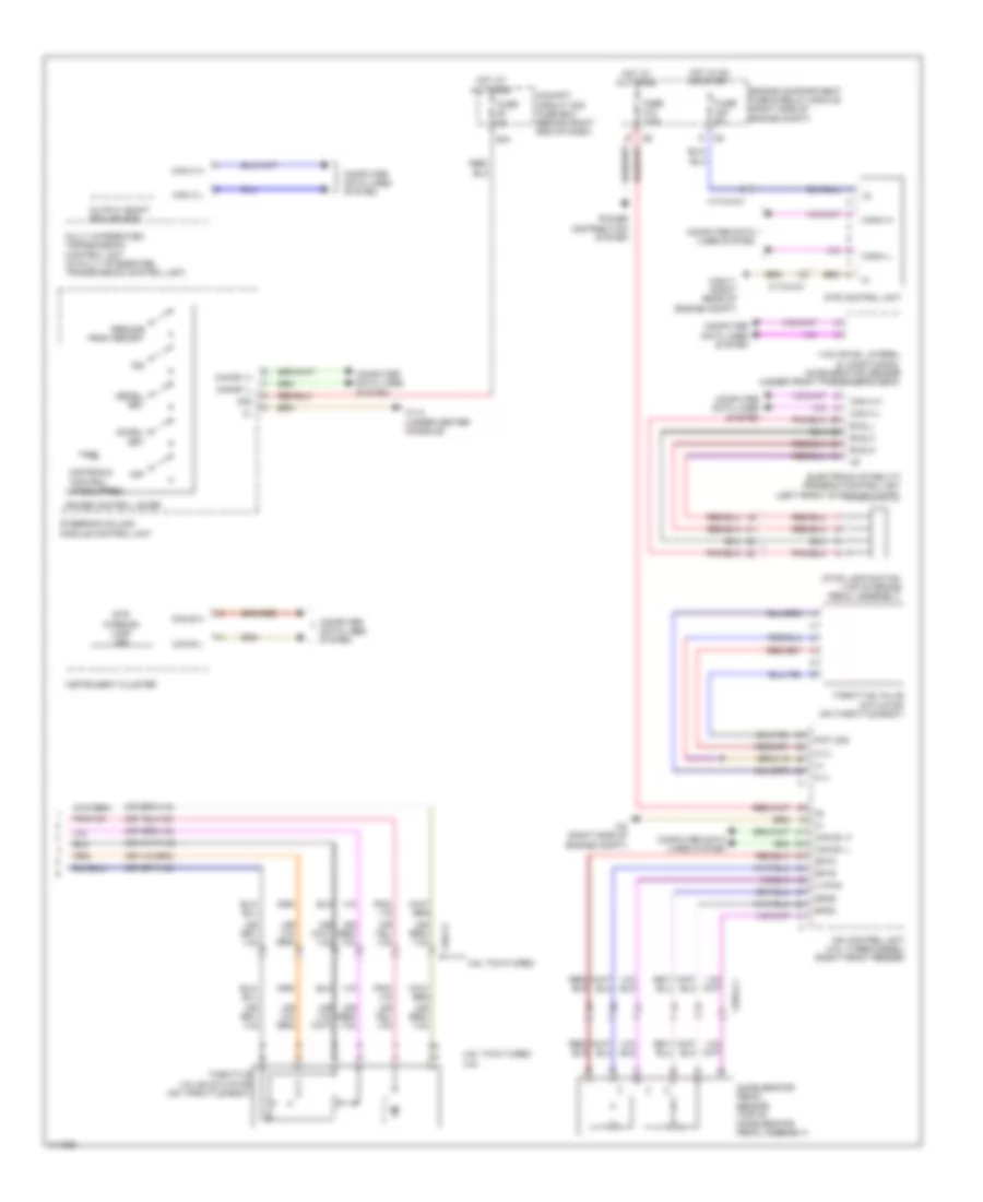
Cruise Control Wiring Diagram (1 of 2) for Mercedes-Benz ML350 BlueTEC 2013

List of elements for Cruise Control Wiring Diagram (1 of 2) for Mercedes-Benz ML350 BlueTEC 2013:
Cruise Control Wiring Diagram (2 of 2) for Mercedes-Benz ML350 BlueTEC 2013
List of elements for Cruise Control Wiring Diagram (2 of 2) for Mercedes-Benz ML350 BlueTEC 2013: