
CRUISE CONTROL
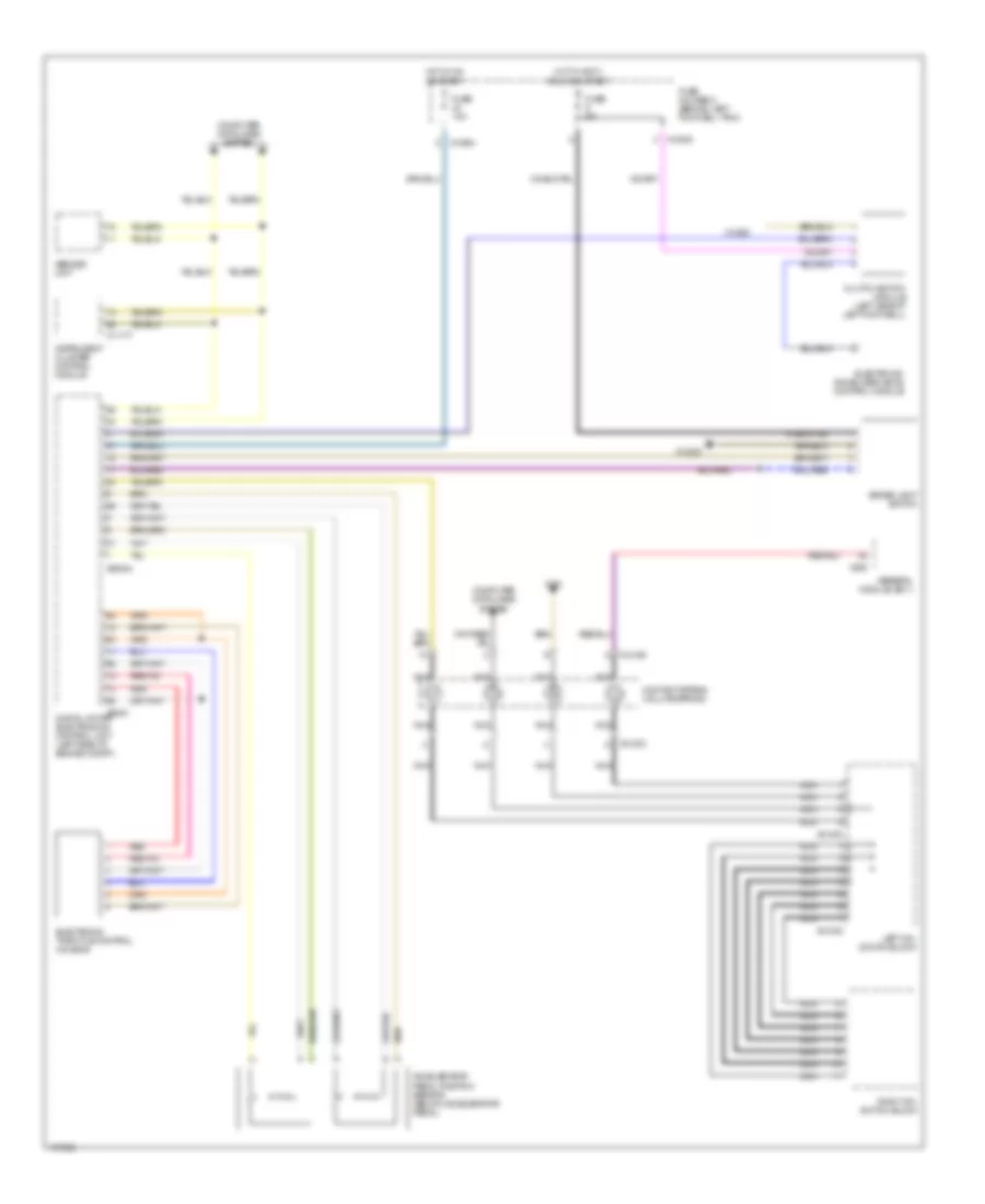
Cruise Control Wiring Diagram for MINI Cooper 2004
List of elements for Cruise Control Wiring Diagram for MINI Cooper 2004:
AIR CONDITIONINGBODY CONTROL MODULESANTI-THEFTCOOLING FANCRUISE CONTROLCOMPUTER DATA LINESANTI-LOCK BRAKESELECTRONIC POWER STEERINGDEFOGGERSENGINE PERFORMANCEEXTERIOR LIGHTSGROUND DISTRIBUTIONHORNHEADLIGHTSINSTRUMENT CLUSTERNAVIGATIONPOWER MIRRORSPOWER SEATSINTERIOR LIGHTSPOWER TOP/SUNROOFPOWER DISTRIBUTIONRADIOPOWER WINDOWSSTARTING/CHARGINGSUPPLEMENTAL RESTRAINTSSHIFT INTERLOCKTRUNK, TAILGATE, FUEL DOORTRANSMISSIONWIPER/WASHER