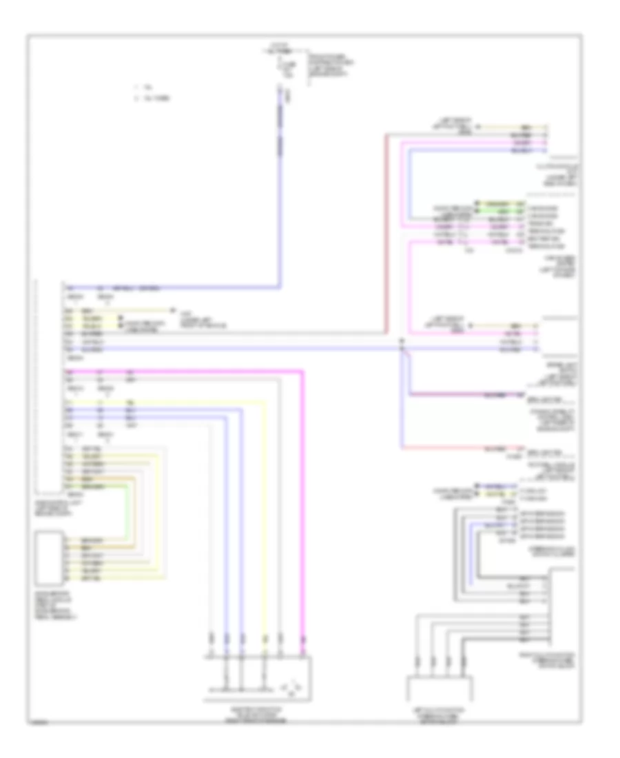
CRUISE CONTROL
Cruise Control Wiring Diagram for MINI Cooper Paceman JCW ALL4 2014
List of elements for Cruise Control Wiring Diagram for MINI Cooper Paceman JCW ALL4 2014:
- (left side of left footwell) x2042
- 1.6l
- 1.6l turbo
- Accelerator pedal module (part of acceleration pedal assembly)
- Brake light switch (left side of left footwell)
- Brk light sig
- Brk test sig
- Can bus sig
- Car access system (left top side of dash)
- Clutch module (m/t) (under left side of dash)
- Computer data lines system
- Dme control unit (left side of engine compt)
- Dynamic stability control (dsc) (left rear of engine compt)
- Electric throttle valve actuator (right front of engine)
- F-can high
- F-can low
- Footwell module (left side of left footwell)
- Front power distribution box (left side of engine compt)
- Fuse f01 7.5a
- Hot at all times
- Left multi-function steering wheel switch block
- Right multi-function steering wheel switch block
- Spi interface sig
- Steering column switch cluster
- Terminal r sig
- Trans sig
- X01006
- X10318
- X14261
- X15
- X167 (under left front of vehicle)
- X1880
- X4013
- X60004
- X60211
- X60212
- X60231
- X60232
 English