CRUISE CONTROL
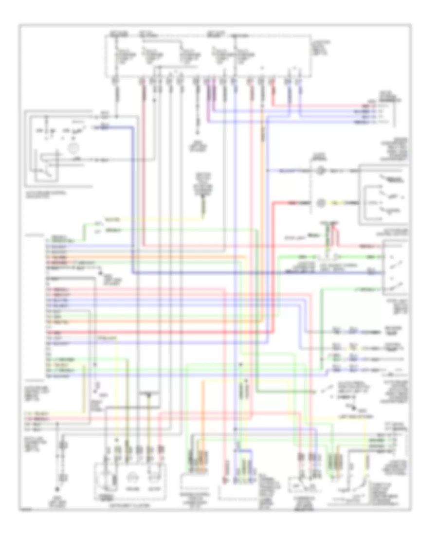
Cruise Control Wiring Diagram for Mitsubishi Expo 1995
List of elements for Cruise Control Wiring Diagram for Mitsubishi Expo 1995:
- a/t
- (below left i/p)
- (expo)
- (left end of dash)
- (right kick panel)
- (summit wagon)
- (summit) c77
- (under center of i/p)
- Auto-cruise control actuator (right rear of engine compartment)
- Auto-cruise control main switch
- Auto-cruise control switch
- Auto-cruise control unit (behind left i/p)
- C24
- C25
- C57
- C58
- C61
- C62
- C63
- C64
- C66
- C67
- C70 c28-2
- C71 (expo)
- Cancel
- Clock spring
- Clutch pedal position switch
- Control valve
- Cruise
- Ctp switch
- D01
- D02
- Data link connector (below left i/p)
- Elc 4-speed automatic transaxle control module
- Engine compartment relay box (right side of engine compartment)
- Engine control module (under right of i/p)
- G202
- G202 (left end of dash)
- G203
- Hot at all times
- Hot in on
- Hot in on or acc
- Hot in on or start
- Ignition switch pin 5 (starting/ charging system)
- Ind
- Instrument cluster
- Iod or storage connector a09x
- Junction block (below left i/p)
- Junction connector (above right kick panel)
- Junction connector (below left i/p)
- M/t
- Multi- purpose fuse 11 10a
- Multi- purpose fuse 17 15a
- Multi- purpose fuse 19 10a
- Multi- purpose fuse 4 10a
- Multi- purpose fuse 7 10a
- Nca
- Not used
- Od off
- Off
- Overdrive switch (on gear selector)
- Red
- Reed
- Release valve
- Resume
- Rheostat
- Set
- Speedo- meter
- Stop light
- Stop light switch (behind left i/p)
- Throttle position sensor (center rear of engine compartment)
 English