CRUISE CONTROL
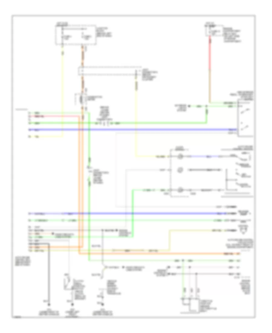
Cruise Control Wiring Diagram, A/T for Mitsubishi Lancer ES 2003

List of elements for Cruise Control Wiring Diagram, A/T for Mitsubishi Lancer ES 2003:
- (behind lower center of dash) joint connentor 6
- Auto cruise control ecu (behind right end of dash)
- Auto cruise control switch
- Auto-cruise control vacuum pump (2.0l: on right front of engine compartment)
- C01
- C02
- C114
- C116
- C118
- C120
- C204
- C214
- C229
- Cancel
- Clock spring
- Combination meter
- Computer data lines system
- Control valve
- Cruise
- Engine compartment relay box (on left side of engine compartment)
- Engine controls system
- Exterior lights system
- Fuse 10 15a
- Fuse 2 7.5a
- Fuse 4 7.5a
- G14 (under front of center console)
- Hot at all times
- Hot in on or start
- Joint connectior 5 (behind instrument cluster)
- Joint connector 6 (behind lower center of dash)
- Junction block (behind left end of dash)
- Main
- Nca
- Off
- Output shaft speed sensor (2.0l: on top right of transaxle)
- Powertrain control module (behind glove box)
- Red
- Release valve
- Resume
- Set
- Starting/ charging system
- Stoplight switch (above brake pedal, on bracket)
- Throttle position sensor (on throttle body)
Cruise Control Wiring Diagram, M/T for Mitsubishi Lancer ES 2003
List of elements for Cruise Control Wiring Diagram, M/T for Mitsubishi Lancer ES 2003:
- (above brake pedal, on bracket) stoplight switch
- (behind lower center of dash) joint connector 6
- Auto cruise control ecu (behind right end of dash)
- Auto cruise control switch
- Auto-cruise control vacuum pump (2.0l: on right front of engine compartment)
- C01
- C02
- C115
- C204
- C214
- C229
- Cancel
- Clock spring
- Clutch pedal position switch (above clutch pedal on bracket)
- Combination meter
- Computer data lines system
- Control valve
- Cruise
- Engine compartment relay box (on left side of engine compartment)
- Engine control module (behind glove box)
- Engine controls system
- Exterior lights system
- Fuse 10 15a
- Fuse 2 7.5a
- Fuse 4 7.5a
- G14 (under front of center console)
- G15 (under left front kick panel)
- Hot at all times
- Hot in on or start
- Joint connector 5 (behind instrument cluster)
- Joint connector 6 (behind lower center of dash)
- Junction block (behind left end of dash)
- Main
- Nca
- Off
- Red
- Release valve
- Resume
- Set
- Throttle position sensor (on throttle body)
- Vehicle speed sensor (on right side of transaxle)