CRUISE CONTROL
2.0L
2.0L, Cruise Control Wiring Diagram for Mitsubishi Lancer ES 2008

List of elements for 2.0L, Cruise Control Wiring Diagram for Mitsubishi Lancer ES 2008:
2.0L TURBO
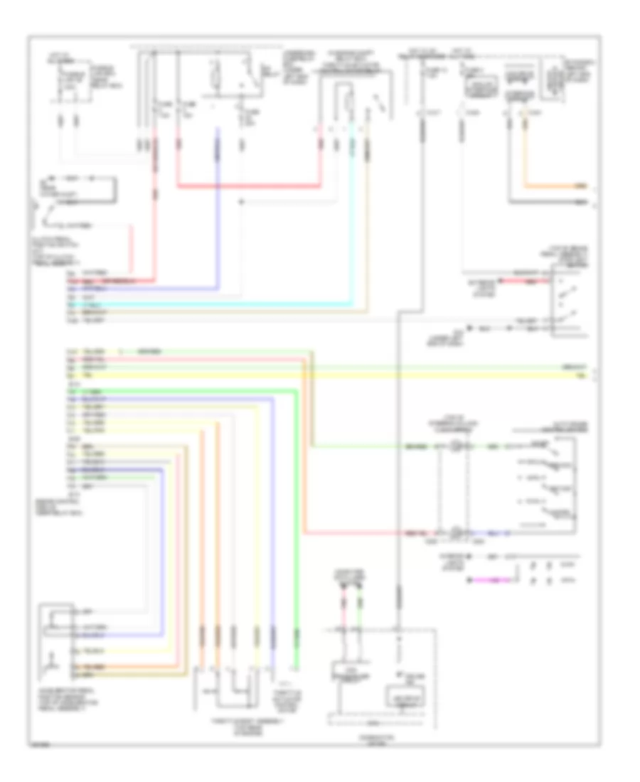
2.0L Turbo, Cruise Control Wiring Diagram (1 of 2) for Mitsubishi Lancer ES 2008
List of elements for 2.0L Turbo, Cruise Control Wiring Diagram (1 of 2) for Mitsubishi Lancer ES 2008:
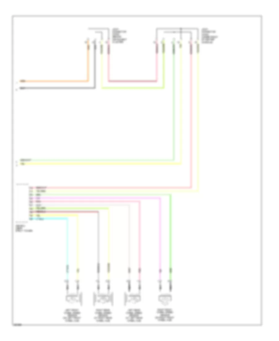
2.0L Turbo, Cruise Control Wiring Diagram (2 of 2) for Mitsubishi Lancer ES 2008
List of elements for 2.0L Turbo, Cruise Control Wiring Diagram (2 of 2) for Mitsubishi Lancer ES 2008: